Hydraulic cooling system and construction machinery with same

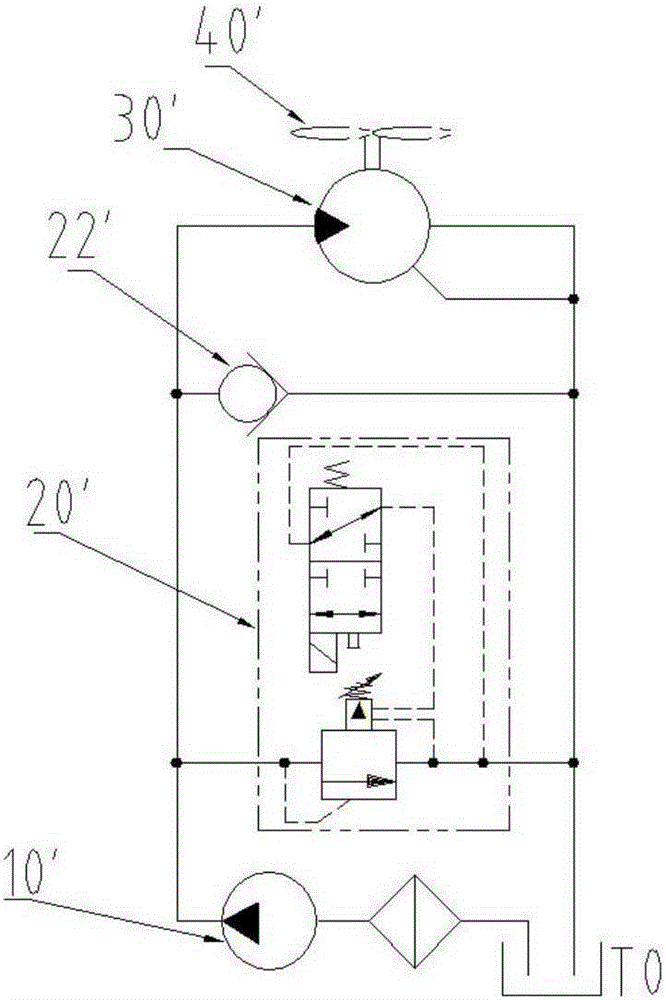
A cooling system and hydraulic technology, applied in the direction of fluid pressure actuation system components, mechanical equipment, fluid pressure actuation devices, etc., can solve the problems of high heat generation in the system, inability to cool on demand, and inability to control the flow rate of the quantitative motor 30', etc. , to achieve good economic benefits

Active Publication Date: 2016-01-20
SHANGHAI ZOOMLION HEAVY IND PILING MACHINERYCO +1
View PDF5 Cites 0 Cited by
  • Summary
  • Abstract
  • Description
  • Claims
  • Application Information

AI Technical Summary

Problems solved by technology

The hydraulic cooling circuit is provided with a temperature sensor, which controls the power on and off of the control end of the electromagnetic overflow valve 20', and then controls the quantitative motor 30' to drive the cooling fan 40' to rotate or not, but it cannot control the quantitative The flow rate of the motor 30' changes with temperature, and it cannot be cooled timely and on demand according to the hydraulic oil temperature, and for the hydraulic system that often works under low-speed and heavy-load conditions, the system generates a large amount of heat, and no pre-cooling method is used to pre-cool the hydraulic system. cool down

Method used


Image

  • Hydraulic cooling system and construction machinery with same
  • Hydraulic cooling system and construction machinery with same
  • Hydraulic cooling system and construction machinery with same

Examples


Embodiment Construction

[0025] The specific embodiments of the present invention will be described in detail below with reference to the accompanying drawings. It should be understood that the specific embodiments described herein are only used to illustrate and explain the present invention, and not to limit the present invention.

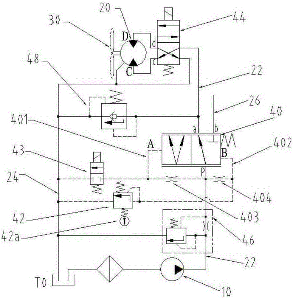
[0026] The embodiment of the present invention provides a hydraulic cooling system, which includes a pump 10, a cooling motor 20, a cooling fan 30 driven and operated by the cooling motor 20, and an oil inlet oil passage 22 connected between the cooling motor 20 and an oil outlet of the pump 10 And an oil return oil path 24 connected between the cooling motor 20 and the oil tank T0. The oil inlet oil path 22 is provided with a hydraulic control reversing valve 40 with an adjustable spool opening, the hydraulic control reversing valve 40 It includes a hydraulic control end A and a hydraulic control end B at opposite ends thereof, an oil inlet P communicated with the pump 10,...


PUM


Abstract

The invention discloses a hydraulic cooling system. The hydraulic cooling system comprises a pump (10), a cooling motor (20), a cooling fan (30), an oil inlet oil way (22) and an oil return oil way (24). The cooling fan (30) is driven by the cooling motor (20) to run, the oil inlet oil way (22) is connected between the cooling motor (20) and the oil outlet of the pump (10), and the oil return oil way (24) is connected between the cooling motor (20) and an oil tank (T0). The hydraulic cooling system is characterized in that a hydraulic control reversing valve (40) with the adjustable aperture of a valve core is arranged on the oil inlet oil way (22); the hydraulic control reversing valve (40) comprises a hydraulic control end A and a hydraulic control end B, an oil inlet P, a working oil port a and a working oil port b. The hydraulic control end A and the hydraulic control end B are located at the two opposite ends of the hydraulic control reversing valve, the oil inlet P is communicated with the oil inlet of the pump (10), the working oil port a is communicated with the cooling motor (20), and the working oil port b is connected with other working oil ways (26). The hydraulic cooling system further comprises a temperature control pressure device, wherein the temperature control pressure device is connected with the hydraulic control end B and enables the pressure of the hydraulic control end B to change along with the temperature of hydraulic oil. The hydraulic cooling system has both the precooling function and the cooling as required function and is good in energy saving and economic returns. Through the hydraulic cooling system, the power of the hydraulic system can be effectively utilized to cool the hydraulic oil.

Description

Technical field [0001] The present invention relates to the field of hydraulic technology, in particular to a hydraulic cooling system and engineering machinery with the same. Background technique [0002] The hydraulic transmission system is commonly used in the field of construction machinery. The hydraulic system will generate a lot of heat under long-term working conditions, which will increase the temperature of the hydraulic oil. In order to realize the on-demand cooling of the hydraulic oil temperature, the hydraulic system is usually equipped with a hydraulic cooling circuit. The cooling capacity of the frequently working hydraulic cooling circuit is automatically adjusted with the hydraulic oil temperature. It is necessary to keep the hydraulic oil temperature within a suitable temperature range. The temperature of the hydraulic oil automatically adjusts the speed of the fan in the cooling circuit to achieve timely cooling on demand to save energy and reduce consumption....

Claims


Application Information

Patent Timeline
Patent Type & Authority Patents(China)
IPC IPC(8): F15B21/04
Inventor 刘亮
Owner SHANGHAI ZOOMLION HEAVY IND PILING MACHINERYCO
Why Eureka
Try Eureka