Wave rotor and rotary thermal separator

A heat separator and wave rotor technology, applied in refrigerators, compressors, lighting and heating equipment, etc., can solve the problems of low system efficiency, reduce energy dissipation, improve cold and heat separation efficiency, and improve efficiency Effect

Pending Publication Date: 2022-05-03
CHINA PETROLEUM & CHEM CORP +1
View PDF14 Cites 0 Cited by
  • Summary
  • Abstract
  • Description
  • Claims
  • Application Information

AI Technical Summary

Problems solved by technology

[0007] The purpose of the present invention is to solve the problem of low system efficiency of the existing multi-stage heat separator using a single-layer channel wave rotor

Method used


Image

  • Wave rotor and rotary thermal separator
  • Wave rotor and rotary thermal separator
  • Wave rotor and rotary thermal separator

Examples


Embodiment 1

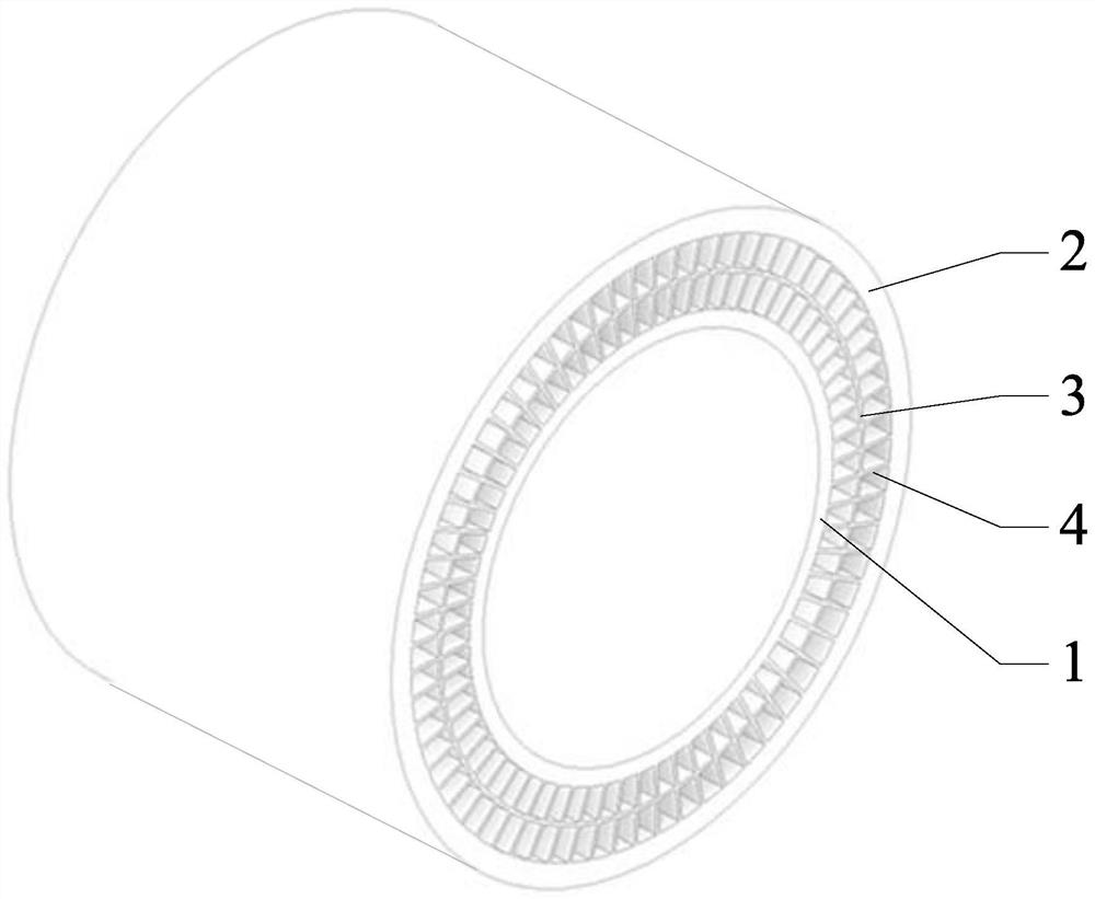
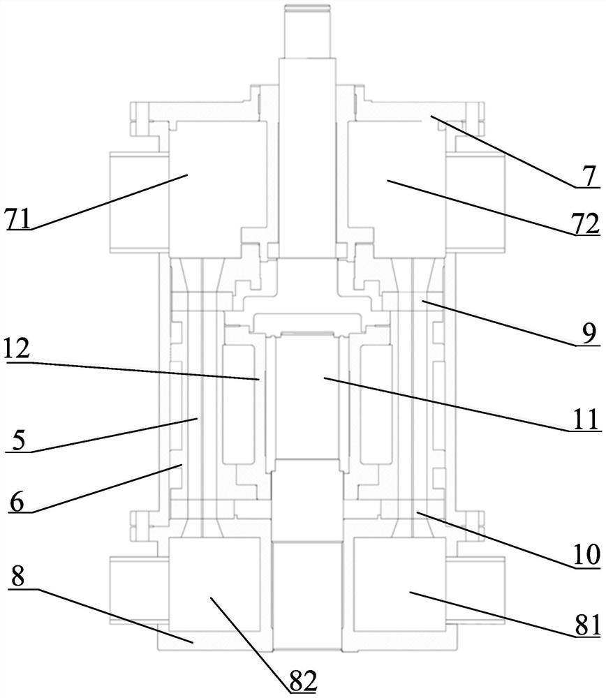
[0040] Example 1: figure 1 A schematic structural diagram of the wave rotor of this embodiment is shown. refer to figure 1 , the wave rotor in this embodiment includes a rotor inner cylinder 1 and a rotor outer cylinder 2, both of which are open-ended at both ends, and the rotor inner cylinder 1 and the rotor outer cylinder 2 are coaxially fixed;

[0041] Between the rotor inner cylinder 1 and the rotor outer cylinder 2, two layers of annular cavities are arranged along the radial direction of the rotor inner cylinder 1;

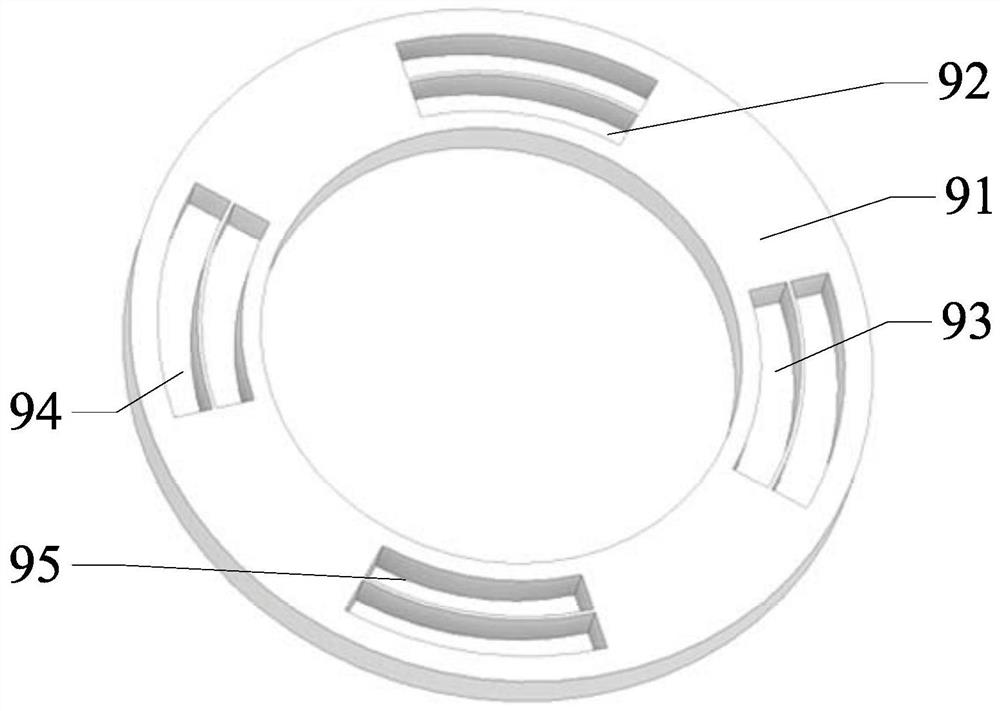
[0042] A plurality of oscillating air passages arranged along the axial length of the annular cavity in each layer are provided in each layer of the annular cavity, and a plurality of oscillating air passages in the same layer of annular cavity are distributed along the circumferential direction of the annular cavity of the layer.

[0043] The wave rotor in this embodiment further includes a sleeve-type partition 3 , which divides the gap between the rotor...

Embodiment 2

[0051] Example 2: figure 1 A schematic diagram of the structure of the wave rotor included in the rotary heat separator of the present embodiment is shown, refer to figure 1 , the wave rotor included in the rotary heat separator of this embodiment includes a rotor inner cylinder 1 and a rotor outer cylinder 2, the rotor inner cylinder 1 and the rotor outer cylinder 2 are both open-ended cylinders, the rotor inner cylinder 1 and the rotor The outer cylinder 2 is fixed coaxially;

[0052] Two layers of annular cavities are arranged between the rotor inner cylinder 1 and the rotor outer cylinder 2 along the radial direction of the rotor inner cylinder 1;

[0053] A plurality of oscillating air passages arranged along the axial length of the annular cavity of each layer are arranged in the annular cavity of each layer, and the plurality of oscillating air passages in the annular cavity of the same layer are distributed along the circumferential direction of the annular cavity of ...

Embodiment 3

[0074] Example 3: figure 1 A schematic diagram of the structure of the wave rotor included in the rotary heat separator of the present embodiment is shown, refer to figure 1 , the wave rotor included in the rotary heat separator of this embodiment includes a rotor inner cylinder 1 and a rotor outer cylinder 2, the rotor inner cylinder 1 and the rotor outer cylinder 2 are both open-ended cylinders, the rotor inner cylinder 1 and the rotor The outer cylinder 2 is fixed coaxially;

[0075] Two layers of annular cavities are arranged between the rotor inner cylinder 1 and the rotor outer cylinder 2 along the radial direction of the rotor inner cylinder 1;

[0076] A plurality of oscillating air passages arranged along the axial length of the annular cavity of each layer are arranged in the annular cavity of each layer, and the plurality of oscillating air passages in the annular cavity of the same layer are distributed along the circumferential direction of the annular cavity of ...


PUM


Abstract

The invention discloses a wave rotor and a rotary thermal separator. The wave rotor comprises a rotor inner cylinder and a rotor outer cylinder, the rotor inner cylinder and the rotor outer cylinder are both cylinders with two open ends, the rotor inner cylinder and the rotor outer cylinder are coaxially and fixedly arranged, and at least two layers of annular cavities are formed between the rotor inner cylinder and the rotor outer cylinder in the radial direction of the rotor inner cylinder. A plurality of oscillation air passages which are arranged along the axial direction of the annular cavity are arranged in each layer of annular cavity, and the plurality of oscillation air passages in the same layer of annular cavity are distributed along the circumferential direction of the layer of annular cavity. The rotary thermal separator comprises the wave rotor. According to the multi-stage thermal separator, the problem that an existing multi-stage thermal separator adopting a single-layer channel wave rotor is low in system efficiency can be effectively solved.

Description

technical field [0001] The invention belongs to the field of gas jet technology, and more specifically relates to a wave rotor and a rotary heat separator. Background technique [0002] Rotary heat separator is a kind of refrigeration equipment close to isentropic decompression, which is mainly composed of nozzle, wave rotor and rotary distributor. The high-energy gas is sprayed into the oscillation tube of the wave rotor through the nozzle, and the existing gas in the oscillation tube is compressed and heated up, and the temperature rise can be as high as about 500°C. The heat generated by compression is transferred from the outer surface of the oscillating tube by natural convection or forced convection. Since the machine is equipped with a rotary distributor, the injection of gas is intermittent. When the gas in the oscillating tube is compressed and heated up, the air intake stops, the gas in the oscillating tube changes its flow direction, undergoes adiabatic expansio...

Claims


Application Information

Patent Timeline
Patent Type & Authority Applications(China)
IPC IPC(8): F25B9/10
CPCF25B9/10
Inventor 郑友林魏蓓李奇丁垚
Owner CHINA PETROLEUM & CHEM CORP
Why Eureka
Try Eureka