Refrigerant recovery system for air-conditioner and air-conditioner

An air conditioner and cold recovery technology, which is applied in the field of air conditioning, can solve the problem of insufficient use of heat, achieve a high degree of automation, accelerate indoor cooling, and improve efficiency

Inactive Publication Date: 2020-07-14
NINGBO AUX ELECTRIC
View PDF10 Cites 0 Cited by
  • Summary
  • Abstract
  • Description
  • Claims
  • Application Information

AI Technical Summary

Problems solved by technology

[0004] The purpose of this application is to provide a cold recovery system of an air conditioner and an air conditioner to solve the problem that heat cannot be fully utilized in the prior art

Method used


Image

  • Refrigerant recovery system for air-conditioner and air-conditioner
  • Refrigerant recovery system for air-conditioner and air-conditioner
  • Refrigerant recovery system for air-conditioner and air-conditioner

Examples


Embodiment Construction

[0038] In order to make the purposes, technical solutions and advantages of the embodiments of the present application clearer, the technical solutions in the embodiments of the present application will be clearly and completely described below in conjunction with the drawings in the embodiments of the present application. Obviously, the described embodiments It is a part of the embodiments of this application, not all of them. Based on the embodiments in this application, all other embodiments obtained by persons of ordinary skill in the art without creative efforts fall within the protection scope of this application.

[0039] Terms used in the embodiments of the present application are only for the purpose of describing specific embodiments, and are not intended to limit the present application. The singular forms of "a", "said" and "the" used in the embodiments of the present application are also intended to include plural forms, unless the context clearly indicates otherw...


PUM


Abstract

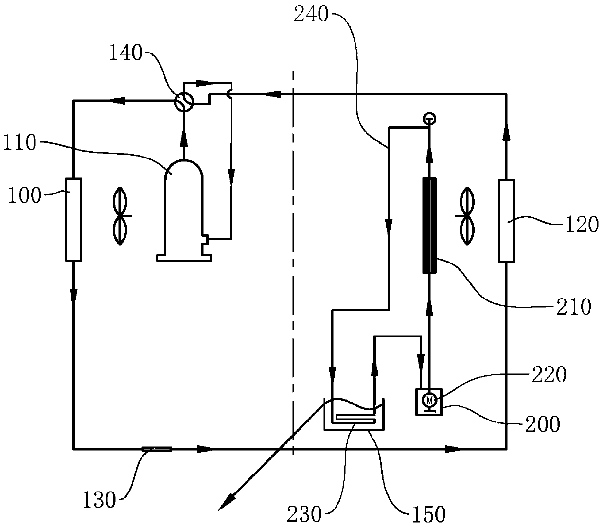
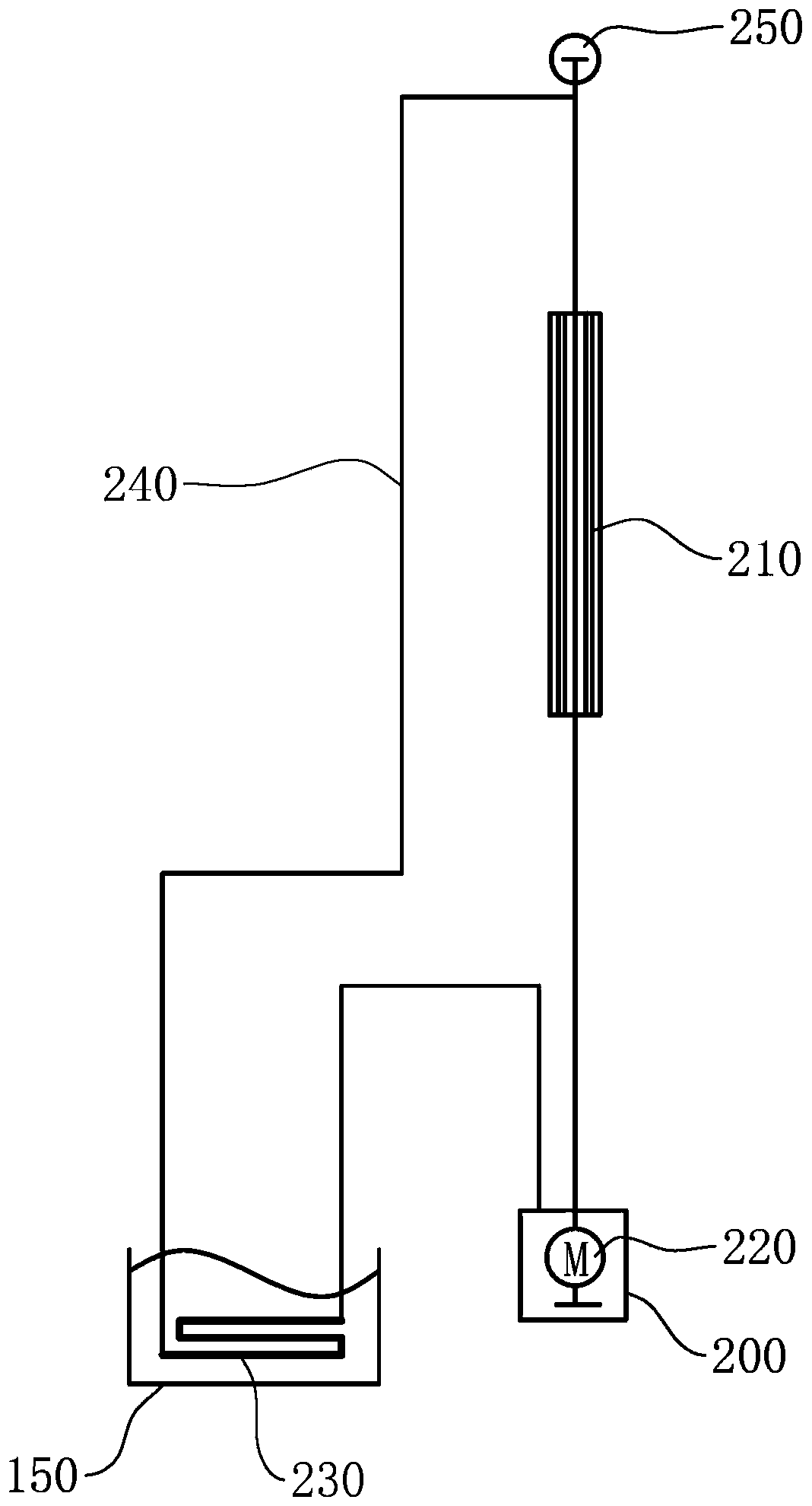
The invention provides a refrigerant recovery system for an air-conditioner and an air-conditioner. The refrigerant recovery system comprises a liquid tank, a heat dissipater, a liquid pump, a refrigerant exchanger and a refrigerant recovery path. The heat dissipater, the liquid box and the liquid pump are connected in series through the refrigerant recovery path. The refrigerant exchanger is connected in series through the refrigerant recovery path. A liquid heat conducting medium is contained in the liquid box. In this way, the heat dissipater is arranged at a wind inlet of an indoor unit ofthe air-conditioner and installed between an evaporator of the air-conditioner and a fan of the air-conditioner. The refrigerant exchanger is installed in a water receiving disc of the air-conditioner. Water in the water receiving disc conducts refrigerant to a refrigerant recovery device, the refrigerant recovery device conducts the refrigerant to the heat dissipater through the refrigerant recovery path, the fan blows airflow to the heat dissipater, the heat dissipater conducts the refrigerant to airflow, the airflow cooled in advance is blown to the evaporator, and fresh air is cooled in advance.

Description

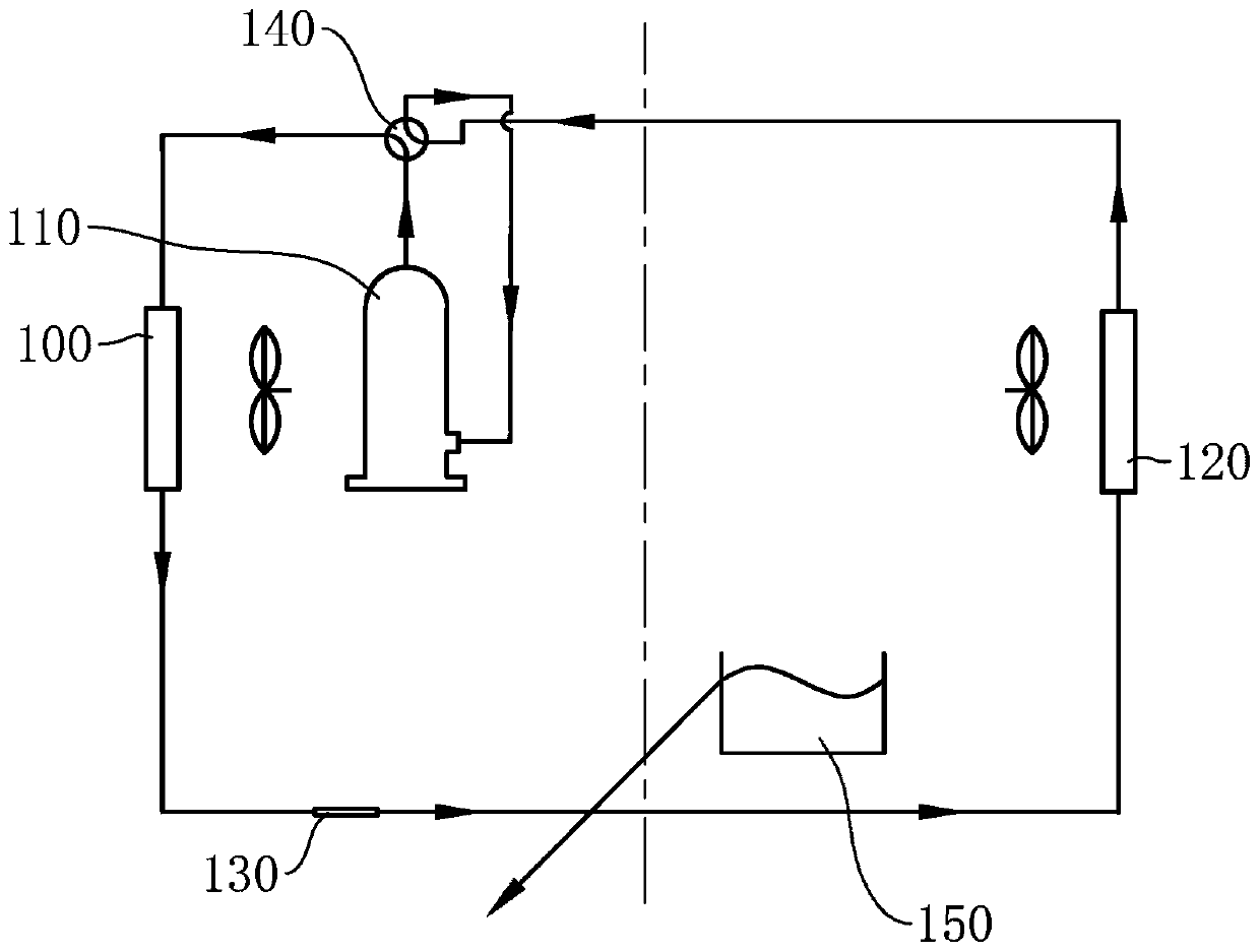
technical field [0001] The present application relates to the technical field of air conditioning, in particular to a cold recovery system of an air conditioner and the air conditioner. Background technique [0002] Existing air conditioners such as figure 1 As shown, it mainly includes a condenser, a compressor, an evaporator, a throttling component, a four-way valve and a water tray. The water tray is used to collect the condensed water generated on the evaporator. In the cooling mode, the refrigerant circulation path is: Compressor exhaust port→four-way valve→condenser→throttle part→evaporator→four-way valve→air return port of compressor; condensate discharge path is: water pan→drain hose→outdoor environment. [0003] The evaporator will produce a small amount of condensed water during the refrigeration cycle, and the temperature is low (generally 8-12°C lower than the indoor ambient temperature). The existing conventional method is to directly discharge this part of con...

Claims


Application Information

Patent Timeline
Patent Type & Authority Applications(China)
IPC IPC(8): F24F12/00F24F13/30
CPCF24F12/00F24F13/30
Inventor 易忠衍王义祥王成卢国军
Owner NINGBO AUX ELECTRIC
Why Eureka
Try Eureka