
LED injection molding module

A technology of injection molding and electronic wires, which is applied in the field of new LED lighting, can solve the problems of long waiting time for curing, unstable LED modules, and low production efficiency, so as to improve production efficiency and yield rate, good waterproof and waterproof Dust effect, the effect of reducing the cost of production process

Inactive Publication Date: 2014-01-15
ZHEJIANG ZHONGZHOU LIGHTING TECH
View PDF0 Cites 5 Cited by
  • Summary
  • Abstract
  • Description
  • Claims
  • Application Information

AI Technical Summary

Problems solved by technology

[0003] At present, most of the LED modules on the market use the traditional welding technology to weld the electronic wires on the PCB board at high temperature to realize the electrical conduction between the electronic wires and the PCB board. This method has low production efficiency and is easy to cause In the process of cascading multiple modules, the positive and negative poles are reversed, false soldering, false soldering, hot pads and other bad phenomena make the LED module potentially unstable, and it is prone to partial or overall failure in the actual use process
[0004] At present, most of the waterproofing of LED modules on the market adopts the method of potting and sealing. This method is costly and complicated. Long, there are air bubbles on the surface, glue overflow and glue leakage, etc. Once defective products are produced, it is difficult to repair them. Therefore, the method of glue filling and sealing is obviously not suitable for large-scale application in LED modules

Method used


Image

  • LED injection molding module
  • LED injection molding module
  • LED injection molding module

Examples


Embodiment Construction

[0028] The LED injection molding module of the present invention will be described below in conjunction with the accompanying drawings and embodiments. The equivalent transformation or improvement of the LED module according to the principle, including the improvement of the shape, size, and material used of the LED module, as well as the addition, deletion and replacement of each part of the structure, to achieve the same function, all belong to this within the scope of invention protection.

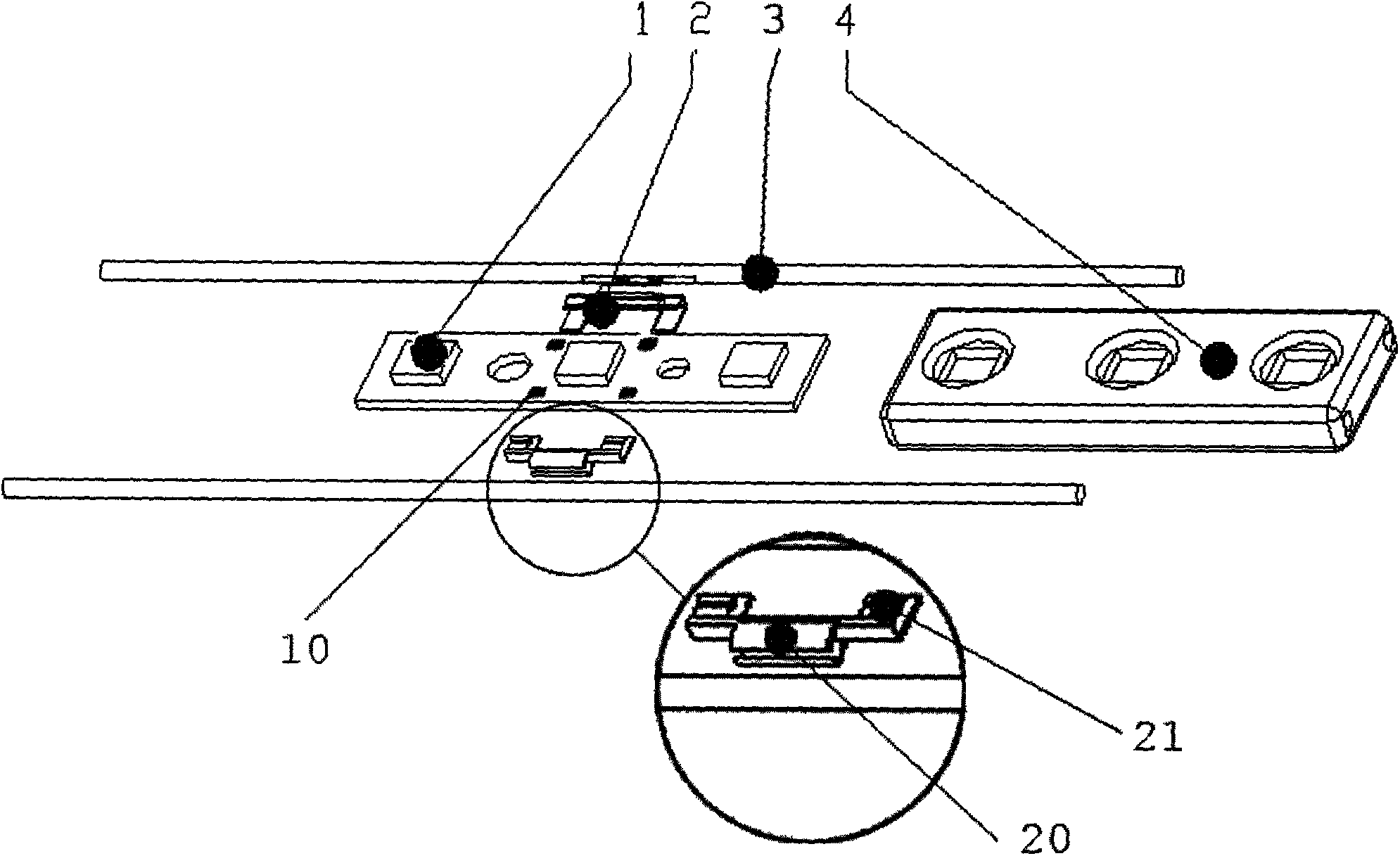
[0029] Such as figure 1 , figure 2 and image 3 As shown, the LED injection molding module described in this example includes a PCB board 1 provided with several LED lamp beads, a U-shaped line card 2, an electronic line 3, and an injection molded housing 4, wherein the electronic line 3 is realized through the U-shaped line card 2 Electrical conduction with the PCB board 1, the injection molded shell 4 tightly wraps the entire PCB board 1, U-shaped line card 2, and electronic wire ...


PUM


Abstract

The invention discloses an LED injection molding module, and relates to the field of novel LED lighting. The LED injection molding module mainly comprises a PCB provided with a plurality of LED lamp beads, a U-type wire clamp, an electronic wire and an injection molding outer shell. A wire clamping groove in one end of the U-type wire clamp is electrically communicated with the electronic wire, a rectangular copper piece at the other end of the U-type wire clamp is in compression contact with a rectangular welding disc on the PCB through pressure generated by the elastic modulus deformation, the electric communication between the electronic wire and the PCB is achieved through the U-type wire clamp, the injection molding outer shell tightly wraps the whole PCB through a sealing waterproof mode, and through holes which allow the electronic wire to penetrate are formed in the two ends of the outer shell. The LED injection molding module is simple in structure, convenient to assemble, simple in production process, low in production cost, high in production efficiency and suitable for large-scale batch production.

Description

technical field [0001] The invention relates to a novel LED lighting field, in particular to an LED injection molding module and its PCB board, line card, and injection molding shell. Background technique [0002] Due to its low power consumption, long life, simple structure, and convenient installation, LED modules are widely used in advertising light boxes, indicator lights, decorative lighting and other places. With the gradual maturity of LED module technology, its application range is wider . [0003] At present, most of the LED modules on the market use the traditional welding technology to weld the electronic wires on the PCB board at high temperature to realize the electrical conduction between the electronic wires and the PCB board. This method has low production efficiency and is easy to cause In the process of cascading multiple modules, the positive and negative poles are reversed, false soldering, false soldering, hot pads and other bad phenomena make the LED m...

Claims


Application Information

Patent Timeline
Patent Type & Authority Applications(China)
IPC IPC(8): F21S2/00F21V23/06F21V31/00F21Y101/02F21K9/20F21Y115/10
Inventor 陈国才费晓明朱晓飚
Owner ZHEJIANG ZHONGZHOU LIGHTING TECH
Learn More