Optical switch collimator baking rack

A technology of collimator and baking rack, applied in the direction of dryer, drying room/container, etc., can solve the problems of collimator falling, affecting production efficiency, unstable collimator quality, etc.

Active Publication Date: 2015-08-12
广西安捷讯电子科技有限公司
View PDF9 Cites 0 Cited by
  • Summary
  • Abstract
  • Description
  • Claims
  • Application Information

AI Technical Summary

Problems solved by technology

At present, most people put the collimator directly into the baking oven for direct baking, but because the collimator placed flat is not conducive to the sufficient flow of glue, the quality of the collimator manufactured by this method is not stable
Therefore, people use the vertical method to bake the collimator. However, because the collimator is thin and long, and the tail is still dragging a long fiber, it is difficult to place the collimator vertically. Therefore, in order to To improve work efficiency, people have designed a variety of baking racks, some of which use double-sided tape to directly paste the collimator on a square rack, but in this method, the collimator often falls off during the baking process. drop phenomenon; some people make a lot of small holes or small grooves on the shelf, and put the collimator into the small holes or small grooves, however, because the tail of the collimator has a long optical fiber, the soft optical fiber is not easy to enter In small holes or small grooves, the production efficiency is seriously affected. Therefore, this problem has become a difficult problem in the industry

Method used


Image

  • Optical switch collimator baking rack
  • Optical switch collimator baking rack
  • Optical switch collimator baking rack

Examples


Embodiment 1

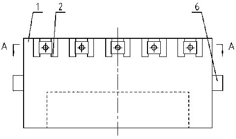
[0021] Taking the collimator 9 of two optical fibers of the optical switch as an example, the principle and process of the baking rack of the optical switch collimator of the present invention are illustrated (see Figure 6 and Figure 7 shown):

[0022] 1. Glue injection

[0023] Put the optical fiber into the glass sleeve as required, and inject glue into the glass sleeve;

[0024] 2. Install spring assembly 3

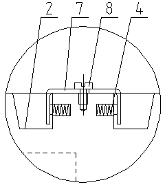
[0025] Install a spring 5 in the spring groove 4 on one side of the wedge-shaped workpiece groove 2, and one end of the spring 5 stretches into the workpiece groove 2, and adjust the appropriate extension amount with the spring compression of the spring 5;

[0026] 3. Install the positioning shrapnel 7

[0027] A U-shaped positioning shrapnel 7 is installed between the two workpiece grooves 2. One side of the positioning shrapnel 7 is fixed on the frame 1 by screws 8. The two U-shaped wings extend into the workpiece groove 2. 5 end contacts;

[0028] 4. Instal...


PUM


Abstract

The invention discloses an optical switch collimator baking frame. The optical switch collimator baking frame is characterized by comprising a machine frame, workpiece grooves and a spring assembly. The machine frame is provided with a plurality of inclined wedge-shaped workpiece grooves, the spring assembly enabling a collimator to be fixed is further installed on one side of every workpiece groove and comprises a spring groove and a spring, the spring is arranged in the spring groove, and one end of the spring extends into the workpiece grooves. The optical switch collimator baking frame has the advantages that the baking frame is simple in structure, injected glue is good in liquidity in a sleeve, the baking frame is glued firmly and stable in quality, the collimator is convenient to install and easy to take out, and the production cost is low.

Description

technical field [0001] The invention relates to an optical switch baking appliance, in particular to an optical switch collimator baking rack. Background technique [0002] Fiber collimator is the basic component of online optical passive devices such as isolator and wavelength division multiplexer. It is made of pigtail and self-focusing lens. light), or couple external parallel (approximately parallel) light into a single-mode fiber. Because the collimator has the characteristics of low insertion loss and high return loss, advanced and high-quality collimators can withstand high power and are favored by many users. The production process of the fiber optic collimator is to insert the optical fiber into the glass sleeve, then inject glue into the glass sleeve, and then put the glue-filled collimator into the oven for drying, so that the optical fiber is tightly fixed on the Inside the glass sleeve, get the semi-finished product of the collimator. At present, most people ...

Claims


Application Information

Patent Timeline
Patent Type & Authority Patents(China)
IPC IPC(8): F26B25/18
Inventor 潘志腾
Owner 广西安捷讯电子科技有限公司
Why Eureka
Try Eureka