Sparse planar formation optimization method based on spatial gain

A space gain and optimization method technology, applied in the field of signal processing, can solve the problems of not taking into account the beam width of the main lobe, not taking into account the peak ratio of the main lobe and the beam width of the main lobe, and not being able to comprehensively evaluate at the same time

Active Publication Date: 2015-06-17
XIDIAN UNIV
View PDF4 Cites 0 Cited by
  • Summary
  • Abstract
  • Description
  • Claims
  • Application Information

AI Technical Summary

Problems solved by technology

However, this method takes the minimum side lobe as the constraint condition and cannot take into account the beam width of the main lobe.
[0007] Most of the current formation optimization methods use the minimum sidelobe level ratio or the main lobe beam width as the cost function, which is limited to fixed formations rather than sparse arrays with better adaptive performance. The optimized cost function cannot take into account the main and side lobes The two important parameters of peak ratio and main lobe beam width cannot be comprehensively evaluated at the same time to obtain formation optimization

Method used


Image

  • Sparse planar formation optimization method based on spatial gain
  • Sparse planar formation optimization method based on spatial gain
  • Sparse planar formation optimization method based on spatial gain

Examples


Embodiment Construction

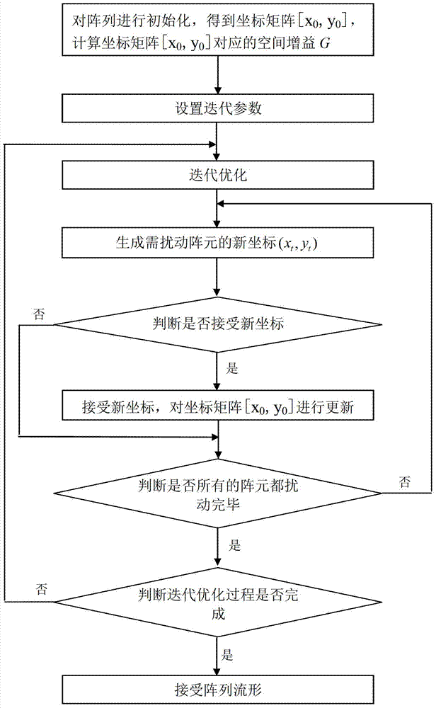
[0061] Reference figure 1 , figure 1 It is a flow chart of the method of the present invention. The method of the present invention is especially optimized for the array manifold of a sparse planar rectangular array. The specific steps of the optimization are as follows:

[0062] Step 1. Initialize the array to obtain the coordinate matrix formed by the coordinate vector of the array element [x 0 ,y 0 ], calculate the coordinate matrix [x 0 ,y 0 ] The corresponding spatial gain G, step 1 includes the following steps:

[0063] Step 1-1: Generate the initial coordinates of the elements on the four corners of the sparse planar rectangular array of the radar antenna:

[0064] x 0 ( 1 ) y 0 ( 1 ) x 0 ( 2 ) y 0 ( 2 ) x 0 ( 3 ) y 0 ( 3 ) x 0 ( 4 ) y 0 ( 4 ) = - 0.5 L x 0.5 L y - 0.5 L x - 0.5 L ...


PUM


Abstract

The invention provides a sparse planar formation optimization method based on spatial gain. The method comprises the following steps that an array is initialized, a coordinate matrix formed by coordinate vectors of array elements is obtained, and spatial gain corresponding to the coordinate matrix is calculated; iteration parameters are set; iterative optimization is carried out on the initialized array, 5-N array elements in the array are sequentially disturbed in each iterative optimization, new coordinates of the array elements generated after each disturbance is finished are judged, the new coordinates meeting the judge conditions replace old coordinates of the array elements, the coordinate matrix is renewed, the interactive process is repeated until a set interactive total number is reached, an array manifold is received, and a coordinate matrix (x0,y0) which is renewed after iterative optimization is used as an array position of a sparse planar matrix. When an angle-directed face array is needed, a cost function can comprehensively evaluate side-lobe level and main-lobe beam width, and by means of the method, the sparse planar array with narrow main-lobe beam width and low side-lobe level can be generated.

Description

Technical field [0001] The invention belongs to the technical field of signal processing, and in particular relates to an optimization method of a sparse planar array manifold. Background technique [0002] Array signal processing technology is widely used in fields such as radar, communications, sonar, navigation, and radio astronomy. One of the important factors affecting the performance of the array is its formation. By optimizing the array formation, the direction of arrival estimation performance and adaptive anti-interference ability of the array can be improved. [0003] Aiming at methods and researches on optimizing the direction of arrival (DOA) estimation performance through array geometry, the existing research results include: [0004] P.J. Bevelacqua et al. published in 2007 IEEE Transactions on Antenna and Propagation in "Optimizing Antenna Array Geometry for Interference Suppression", they proposed to obtain the optimized array manifold through simulated annealing alg...

Claims


Application Information

Patent Timeline
Patent Type & Authority Patents(China)
IPC IPC(8): G01S3/00
CPCG01S3/06G01S3/74G01S3/8006
Inventor 曾操马义彪王兰美李军廖桂生陶海红
Owner XIDIAN UNIV
Why Eureka
Try Eureka