Earthquake stratum fracture crack density retrieval method and system
A fracture density and fissure technology, which is applied in the field of seismic stratigraphic fissure and fracture density inversion methods and systems, can solve problems such as the quantitative evaluation of fractured oil and gas reservoirs that cannot meet the requirements for calculating oil and gas reserves in fractured oil and gas reservoirs.
- Summary
- Abstract
- Description
- Claims
- Application Information
AI Technical Summary
Problems solved by technology
Method used
Image
Examples
Embodiment 1
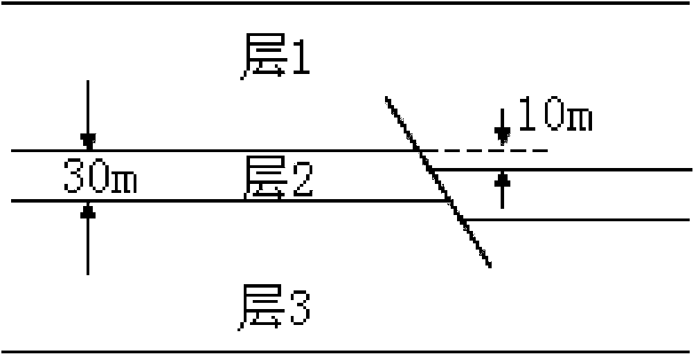
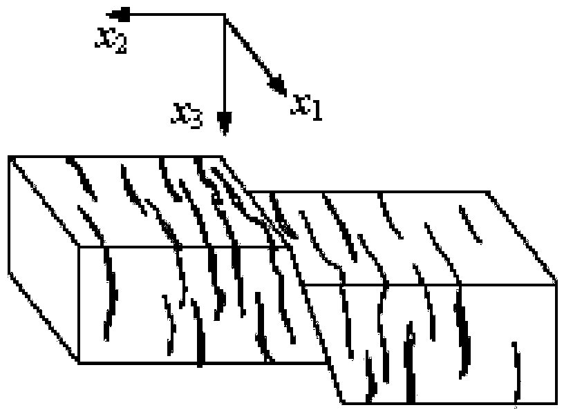
[0060] This example is a three-layer geological model with faults, the model size is 1000m×800m; the grid size is: DX=DZ=10m, the fault drop is 10m, the upper and lower layers are the same, the middle layer has developed cracks, and the thickness of the cracked layer Is 30m, the crack direction and x 1 The axes are parallel, and the model parameters are shown in Table 1:
[0061] Layer number
λ(GPa)
μ(GPa)
ρ(g / cm 3 )
e
Vp(m / s)
Tier 1
13.087
11.454
2.4
0.0
3870
[0062] Layer 2
10.116
5.734
2.3
0.08
3060
Layer 3
13.087
11.454
2.4
0.0
3870
[0063] Table 1
[0064] The corresponding model diagram is as Figure 1a , Figure 1b as well as Figure 1c Shown. The depth direction of the fracture density rock changes as figure 2 As shown by the solid line, fissures are developed near the fault, and the density of fissures on both sides gradually decreases, such as image 3 Shown by the solid line.
[0065] Such as Figure 4 As shown, this embodiment is a flow chart of a me...
Embodiment 2
[0161] It is a five-layer geological model, and the model size and grid size are the same as in the first embodiment. The third layer and the fourth layer are developed with cracks. The crack density of the third layer is 0.12, and the crack direction is the same as x 1 The axis angle is -350, the crack density of the fourth layer is 0.06, and the crack direction is x 1 The shaft angle is -750, the model of Example 2 is as Figure 7 As shown, the corresponding parameters are shown in Table 2.
[0162] Layer number
Thickness(m)
ρ(g / cm 3 )
V p(m / s)
Vs(m / s)
e
θ (degree)
1
400
2400
3640
1750
0
0
2
70
2300
3157
1579
0
0
3
50
2450
3513
1887
0.12
-35
4
80
2500
3726
2053
0.06
-75
5
600
2400
3640
1750
0
0
[0163] Table 2
[0164] Three-component seismic data of 30 shots were collected on the model, Figure 8 Perform inversion for the data of a certain shot, and the specific implementation steps are basically the same as those in the first embodiment. The differences ar...
Embodiment 3
[0170] Such as Picture 10 Shown is a structural diagram of a seismic formation crack density inversion system of the present invention, including the following units:
[0171] The preprocessing unit 1001 is configured to collect three-component seismic data and preprocess the three-component seismic data to obtain measured three-component shot set data;
[0172] The pre-processing of the three-component seismic data includes: two horizontal component rotation, three-component static correction, surface consistent amplitude compensation and pre-stack noise removal.
[0173] The depth domain longitudinal wave velocity and formation mass density calculation unit 1002 is used to extract common center point gather data from the vertical component shot collection data in the three-component shot collection data, and perform longitudinal wave velocity analysis, time domain longitudinal wave velocity calculation and longitudinal wave Time-depth conversion to obtain the longitudinal wave vel...
PUM
 Abstract
Description
Claims
Application Information
 - R&D
- Intellectual Property
- Life Sciences
- Materials
- Tech Scout
- Unparalleled Data Quality
- Higher Quality Content
- 60% Fewer Hallucinations
Browse by: Latest US Patents, China's latest patents, Technical Efficacy Thesaurus, Application Domain, Technology Topic, Popular Technical Reports.
© 2025 PatSnap. All rights reserved.Legal|Privacy policy|Modern Slavery Act Transparency Statement|Sitemap|About US| Contact US: help@patsnap.com


