see-through display device

A see-through display and device technology, applied in instruments, optical components, optics, etc., can solve the problems of the picture display quality to be improved, the coupling efficiency is not high, the field of view is narrow, etc., to reduce the loss of light wave energy, and the output image is clear Realistic picture effect

Inactive Publication Date: 2015-09-16
UNIV OF SHANGHAI FOR SCI & TECH
View PDF5 Cites 0 Cited by
  • Summary
  • Abstract
  • Description
  • Claims
  • Application Information

AI Technical Summary

Problems solved by technology

However, this invention patent also has the problems of narrow field of view, low coupling efficiency, and image display quality that needs to be improved.

Method used


Image

  • see-through display device
  • see-through display device
  • see-through display device

Examples


Embodiment 1

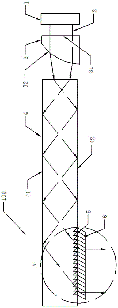
[0024] figure 1 It is a schematic structural diagram of a see-through display device in an embodiment of the present invention.

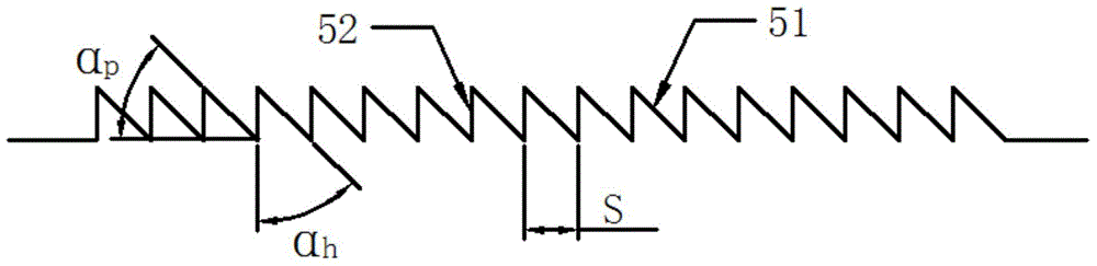
[0025] figure 2 for figure 1 Schematic diagram of the structure of the tooth-shaped slot unit in the middle perspective display device.

[0026] Figure 4 for figure 1 The partial enlarged view corresponding to the letter A of the device is shown in the middle perspective.

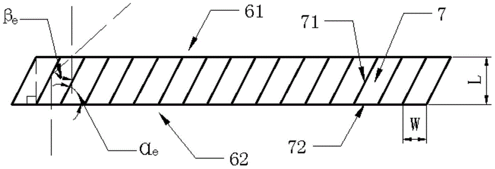
[0027] like figure 1 , figure 2 and Figure 4 As shown, the see-through display device 100 based on the tooth-shaped plane extended optical waveguide provided by the present invention sequentially includes: a display light source 1, which is used to emit collimated display light waves 2 for displaying desired images; a lenticular lens 3, which changes the collimated display light waves 2, output the coupled light wave; the planar waveguide substrate 4, reflect and propagate the coupled light wave to form a total reflection light wave; the tooth-shaped groove unit 5, co...


PUM


Abstract

The invention discloses a perspective display device based on tooth-shaped plane expanding optical waveguide. The perspective display device comprises a display light source, a column-shaped lens, a plane waveguide substrate, a tooth-shaped groove unit and a light wave beam expanding set in sequence. The display light source is used for emitting collimation display light waves for displaying needed images. The column-shaped lens changes the route angle of the collimation display light waves and outputs coupling light waves. The plane waveguide substrate carries out reflecting transmission on the coupling light waves to form full reflecting light waves. The tooth-shaped groove unit forms a coupling output unit and carries out coupling on the full reflecting light waves and then outputs display light waves. The light wave beam expanding set carries out plane expanding on the display light waves which are output as light signals capable of being identified by a client. The whole perspective display device has the advantages of being compact in structure, small in size, light in weight and simple in manufacturing technology, a large view field is achieved, and the perspective display device has the obvious advantages that the output images are clear, image displaying quality is high, and verisimilitude of the displayed images is effectively guaranteed.

Description

technical field [0001] The invention relates to a display device, in particular to a see-through display device based on tooth-shaped plane-expanded optical waveguides. Background technique [0002] At present, display technologies such as flat panel display, wearable display, and notebook display usually rely on optical devices to transmit image information to be displayed. For example, the overhead wearable display system relies on optical lenses and prisms to virtually display pictures at a certain distance in front of the human eye. Without affecting the visibility of the human eye to the surrounding scenery, it can walk while browsing information, which enhances the sense of reality. The main core optical components of such systems are composed of three parts: light wave input coupling device, light wave transmission substrate and light wave output coupling device. Although a large field of view can be obtained by conventional imaging methods, the overall weight and vo...

Claims


Application Information

Patent Timeline
Patent Type & Authority Patents(China)
IPC IPC(8): G02B27/01G02B17/08
Inventor 张文君张庆
Owner UNIV OF SHANGHAI FOR SCI & TECH
Why Eureka
Try Eureka