Information processing system, output control device, and data generation device
An information processing system and data control technology, applied in the direction of electrical digital data processing, response error generation, electrical testing/monitoring, etc., to achieve the effect of ensuring failure safety, low cost, and realizing the system
- Summary
- Abstract
- Description
- Claims
- Application Information
AI Technical Summary
Problems solved by technology
Method used
Image
Examples
Embodiment 1
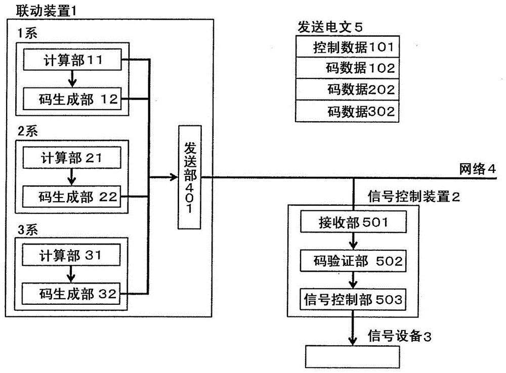
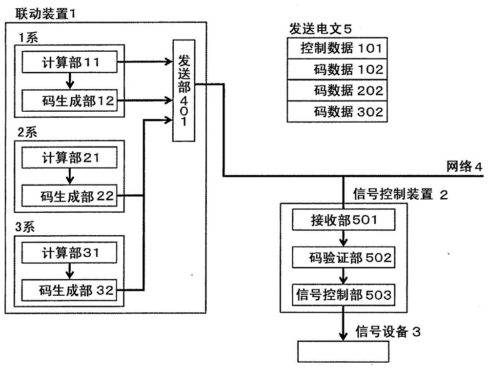
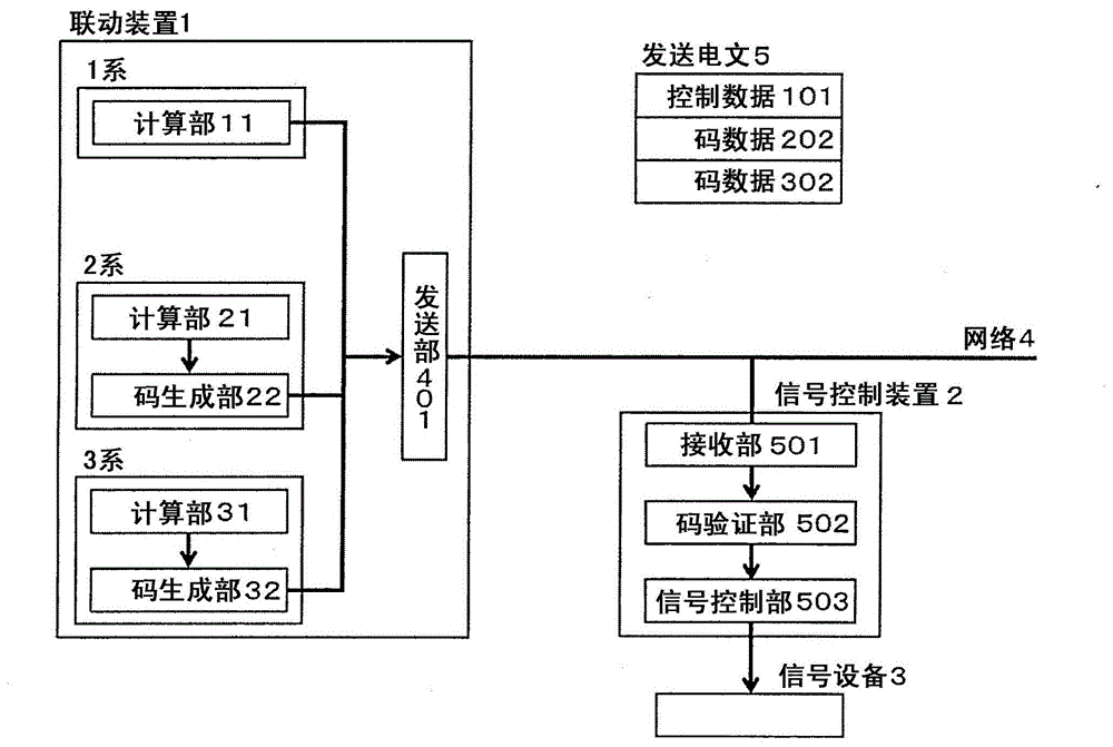
[0049] In this embodiment, as a multi-system information processing system, an interlocking device 1 including three computing units is assumed. In addition, it is assumed that the linkage device 1 is connected to the signal control device 2 through the network 4 , and the signal control device 2 is connected to the signal device 3 . In addition, the present invention may also be composed of a double system based on the 1-series and 2-series, or a multiple system of 3 or more lines. In addition, the multi-system information processing system to which the present invention is applied is not limited to signaling equipment in railways, and can be applied to various equipment by reading the signal control device 2 and the signaling equipment 3 as output control devices and control target equipment, respectively. Likewise, the interlocking device 1 can be read as a data generating device that generates control data for controlling the controlled device from input data. Moreover, t...
Embodiment 2
[0081] In this embodiment, it is described that the transmitting unit 411 in the interlocking device 1 generates an error detection code data 402 based on the data calculated by the code generating units (13, 23, and 33) of each system, and converts the control data 101 and the formed error The detection code data 402 is sent to an instance of the signal control device 2 . Figure 5 It is the structure in Example 2. The interlocking device 1, the signal control device 2, the signaling device 3, the network 4, and the transmission message 5 correspond to those of the first embodiment, and have the same configuration unless otherwise specified.
[0082] As a method of constructing verifiable one code data from code data received from a plurality of departments, for example, secret function distribution can be applied. The so-called secret function distribution is a method of performing distributed encoding of a secret function on a plurality of systems (i), and is as follows: I...
Embodiment 3
[0088] In this embodiment, an example in which the code pre-verification unit 42 is provided in the interlocking device 1 is shown. Figure 6 This configuration is shown in . The interlocking device 1, the signal control device 2, the signaling device 3, the network 4, and the transmission message 5 correspond to those of the first embodiment, unless otherwise specified, they have the same configuration.
[0089] Before the control data 101 is transmitted to the signal control device 2 , the code verification is performed by the code pre-verification unit 42 , thereby preventing erroneous control data 101 from flowing out of the interlocking device 1 . According to this, compared with Example 1, abnormality of the control data 101 can be detected earlier, and it becomes possible to pinpoint, eliminate, and maintain the cause. In addition, since the interlock device 1 can verify the control data, according to the configuration of this embodiment, the transmitter reduces the fa...
PUM
 Abstract
Description
Claims
Application Information
 - R&D
- Intellectual Property
- Life Sciences
- Materials
- Tech Scout
- Unparalleled Data Quality
- Higher Quality Content
- 60% Fewer Hallucinations
Browse by: Latest US Patents, China's latest patents, Technical Efficacy Thesaurus, Application Domain, Technology Topic, Popular Technical Reports.
© 2025 PatSnap. All rights reserved.Legal|Privacy policy|Modern Slavery Act Transparency Statement|Sitemap|About US| Contact US: help@patsnap.com


