
A positioning device, rsu and application system based on dsrc technology

A technology for positioning devices and positioning antennas, which is applied to instruments, ticketing equipment, etc., can solve problems such as low positioning accuracy, positioning errors, and large fluctuations in microwave signal field strength, achieving high accuracy, avoiding errors in deducting fees, and solving car-following problems interference effect

Active Publication Date: 2016-08-03
SHENZHEN GENVICT TECH
View PDF9 Cites 0 Cited by
  • Summary
  • Abstract
  • Description
  • Claims
  • Application Information

AI Technical Summary

Problems solved by technology

An existing vehicle positioning technology applied to the ETC system, such as a Chinese invention patent with an application date of December 27, 2010, an application number of 201010608098.0, and an invention title of "A Positioning Device and Method for Vehicle-mounted Units in an ETC System" , it sets a plurality of receiving antennas in different positions in the RSU, which are used to receive the microwave signals sent by the OBU, and compares the field strength of the microwave signals received by different receiving antennas, and combines the positions of different receiving antennas to perform OBU Positioning, this method is easily affected by multipath fading, so that the field strength fluctuation of the received microwave signal changes greatly, which is easy to cause positioning errors, so the positioning accuracy is relatively low

Method used


Image

  • A positioning device, rsu and application system based on dsrc technology
  • A positioning device, rsu and application system based on dsrc technology
  • A positioning device, rsu and application system based on dsrc technology

Examples


Embodiment 1

[0031] This embodiment implements vehicle positioning based on the information interaction between the RSU and the OBU. Among them, the RSU includes an outdoor unit and an indoor unit. The RSU outdoor unit has a receiving antenna for sending microwave signals to the OBU and receiving microwave signals from the OBU. The RSU outdoor unit is usually installed above the road or on the side of the road. The RSU indoor unit is used for Control the RSU outdoor unit and process the information received and sent by the RSU outdoor unit; the OBU also has an antenna for sending microwave signals to the RSU and receiving microwave signals from the RSU. The OBU is usually installed in the vehicle, such as fixed on the vehicle on the front windshield.

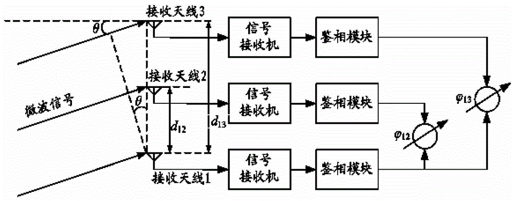
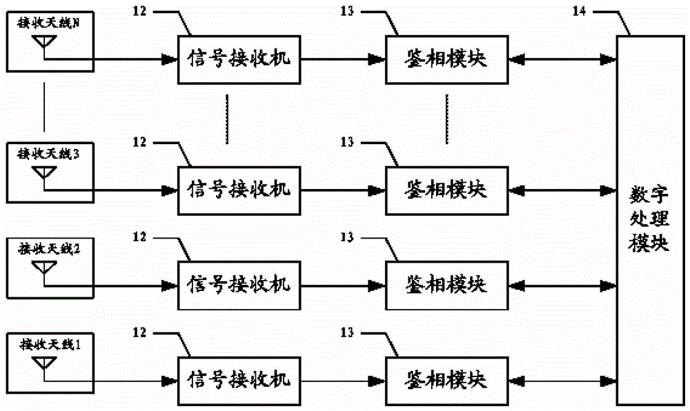
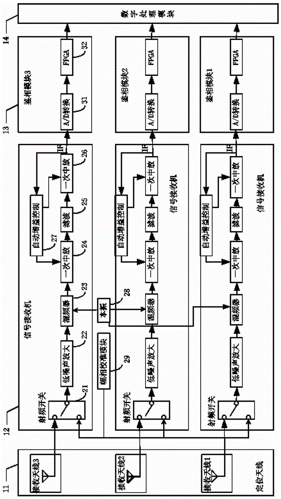
[0032] Such as Figures 1 to 4 As shown, the positioning device 100 of the present application mainly includes a positioning antenna 11 , a signal receiver 12 , a phase detection module 13 and a digital processing module 14 .

[0033] Wher...

Embodiment 2

[0070] Different from Embodiment 1, in the positioning device 100 of this embodiment, the digital processing module 14 can also use other methods to calculate the azimuth angle θ of the microwave signal, for example, in the antenna group of the positioning antenna, the receiving antenna 1 is set at the receiving antenna 2 and receiving antenna 3, firstly by:

[0071] (Formula 6)

[0072] (Formula 7)

[0073] Calculate the phase difference and difference between

[0074] (Formula Eight)

[0075] because The phase difference that can be obtained by and Then you can use formula 8 to get the following formula to determine θ:

[0076] (formula nine)

Embodiment 3

[0078]The positioning antenna of this embodiment includes more than four receiving antennas, so there are multiple different antenna groups formed by these receiving antennas. In this embodiment, multiple antenna groups can be selected according to specific needs. The digital processing module 14 is used to The azimuth angle θ of the microwave signal corresponding to each antenna group is calculated in the manner of one or embodiment two, and the numerical values ​​of multiple azimuth angles θ are obtained. Due to measurement, data processing and calculation errors, there must be a certain difference between these numerical values, so the figures The processing module 14 takes the mean value of the azimuth angle θ of the microwave signals corresponding to the multiple antenna groups, that is, sums all the calculated values ​​of the azimuth angle θ and takes the average value, and uses the mean value to calculate the positioning information of the OBU, thereby improving the calcu...


PUM


Abstract

This application discloses a positioning device, RSU and application system based on DSRC technology. The positioning device includes: at least one positioning antenna, and the positioning antenna includes at least three receiving antennas; The received microwave signal from the same vehicle-mounted unit is input to the phase detection module; the phase detection module: used to respectively obtain the digital phase information corresponding to the microwave signal received by the receiving antenna; the digital processing module: used to receive the microwave signal according to the receiving antenna The phase difference between the signals calculates the azimuth θ of the microwave signal, and calculates the positioning information of the on-board unit according to the azimuth θ. The positioning device of the present application has high positioning accuracy, can effectively solve the problems of adjacent road interference and vehicle-following interference, and ensure the normal operation of the DSRC application system.

Description

technical field [0001] The present application relates to the field of intelligent transportation (ITS: Intelligent Transportation System), in particular to a positioning device, RSU and application system based on dedicated short-range communication (DSRC: Dedicated Short Range Communication) technology. Background technique [0002] In the electronic toll collection (ETC: ElectronicTollCollection) system, the roadside unit (RSU: RoadSideUnit) set on the road and the on-board unit (OBU: On-boardUnits) installed on the vehicle are in the process of information interaction through DSRC technology. The RSU should only communicate with the OBU within the lane area covered by the RSU antenna to maintain the accuracy and reliability of communication and charging. However, sometimes, the RSU cannot determine and identify whether the OBU is in the lane area covered by the RSU antenna, so the RSU may communicate with all OBUs that send out response signals. If the reflected RSU sig...

Claims


Application Information

Patent Timeline
Patent Type & Authority Patents(China)
IPC IPC(8): G07B15/06
Inventor 李兴锐徐根华杨成李洪波
Owner SHENZHEN GENVICT TECH
Learn More