Real-time on-line self-diagnosis method and system for video monitoring equipment failure

A technology for video surveillance and equipment failure, applied in the field of video surveillance equipment, can solve the problems of slow troubleshooting, high cost of human resources, and low degree of automation and intelligence, so as to improve maintenance and repair efficiency and reduce maintenance and repair. cost, increased intelligence, and effectiveness of application benefits

Inactive Publication Date: 2014-01-15
支录奎
View PDF5 Cites 13 Cited by
  • Summary
  • Abstract
  • Description
  • Claims
  • Application Information

AI Technical Summary

Problems solved by technology

With the rapid increase in the number of equipment and instruments used outdoors or remotely, whether the front-end equipment is running, whether the video image is sent back, whether the communication link is normal, whether the quality of the picture recording is up to standard, etc. have become problems that plague the management department. The equipment adopts the maintenance mode of regular inspection, human diagnosis, post-event disposal, and on-site maintenance. The degree of automation and intelligence is low, and it takes up a lot of human resources and the troubleshooting speed is slow.
How to solve the current outdated maintenance mode of video surveillance equipment and instruments, improve the intelligence and application efficiency of remote equipment, and reduce maintenance costs on a large scale have become bottlenecks and obstacles that restrict the improvement of social security management and control.

Method used


Image

  • Real-time on-line self-diagnosis method and system for video monitoring equipment failure

Examples


Embodiment Construction

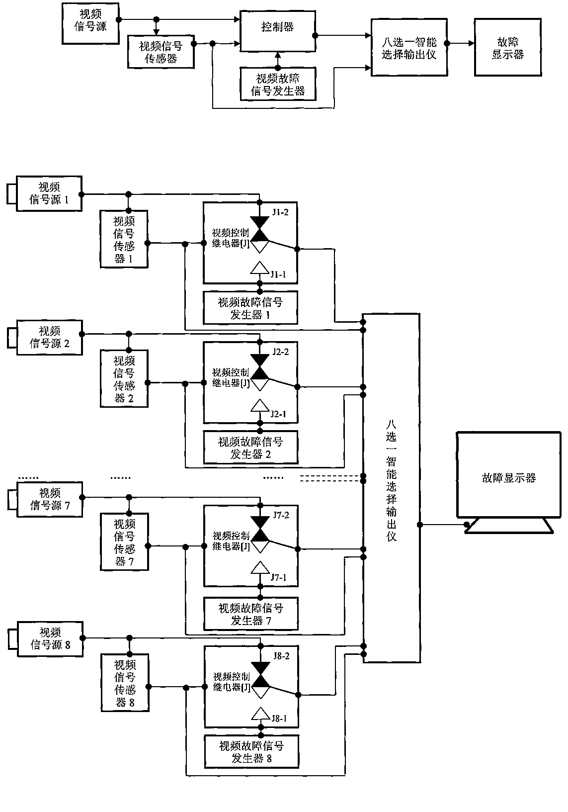
[0012] In order to effectively solve the current backward maintenance mode of video surveillance equipment and instruments, improve the intelligence and application efficiency of remote equipment, reduce maintenance and repair costs, effectively relieve the maintenance work pressure of management departments, save social management and operation costs, and enable remote video The use and maintenance of monitoring equipment and instruments are more convenient and humanized.

[0013] The invention belongs to an online self-diagnosis system for the operating status of video monitoring equipment, which can remotely monitor the operating status of video monitoring equipment online in real time. , the system can automatically detect and judge in real time, automatically alarm the fault, and upload and output the fault information. For the first time, it is proposed to introduce video signal sensing into the field of equipment fault maintenance, which greatly improves the maintenance...


PUM


Abstract

The invention belongs to a real-time on-line self-diagnosis method and system for a video monitoring equipment failure. A real-time on-line self-diagnosis system is formed by a video signal sensor, a video signal control relay, a video failure signal generator, an intelligent one-out-of-eight selection output instrument and a failure displayer. The video signal sensor additionally installed on a video signal source is adopted to induce and detect the state of a video signal in real time, and automatic induction detection, failure precise warning, real-time displaying of failure equipment related information and other functions of the video monitoring equipment failure are achieved. The method comprises the following steps that (1) the video signal sensor induces the video signal; (2) the video signal control relay carries out gating control; (3) the video failure signal generator is closed and powered on; (4) the intelligent one-out-of-eight selection output instrument selects failure information needing to be output; (5) the video failure information is output and displayed. According to the real-time on-line self-diagnosis method and system, an existing failure maintenance mode is innovated to an on-line real-time self-diagnosis mode, lots of manpower, material resources and maintenance cost are saved, and far-reaching influences on social management innovation are achieved.

Description

technical field [0001] The invention belongs to an automatic diagnosis system for remote monitoring of the operating status of video monitoring equipment, which aims at the chronic problems of video monitoring equipment and instruments used outdoors or remotely, such as long period of time for fault judgment, manual on-site troubleshooting and repair of faults, and post-disposal maintenance and repair mode. Using technical means to solve a series of problems such as the low degree of automation and intelligence of video surveillance equipment fault maintenance, the high cost of human resources, and the slow speed of fault processing. The invention has positive practical significance for improving the social management ability of public security organs and reducing missed detection of police incidents, and has far-reaching influence in the field of social management innovation. Background technique [0002] In recent years, the construction of my country's urban alarm and mon...

Claims


Application Information

Patent Timeline
Patent Type & Authority Applications(China)
IPC IPC(8): H04N17/00H04N7/18
Inventor 支录奎张鹏飞赵建敏赵文涛宋沂昕贾宝银
Owner 支录奎
Why Eureka
Try Eureka