
Method and apparatus for compressing/loading stent-valves

A valve and equipment technology, which is applied in the field of loading stents for delivery catheters, can solve problems such as being too large

Active Publication Date: 2014-01-15
SYMETIS
View PDF7 Cites 28 Cited by
  • Summary
  • Abstract
  • Description
  • Claims
  • Application Information

AI Technical Summary

Problems solved by technology

[0005] The challenge is to provide a technique for compressing stent-valve that is relatively simple and intuitive to use, is inexpensive to implement, utilizes equipment that is not overly bulky and easily sterilizable, and also avoids the problems discussed above

Method used


Image

  • Method and apparatus for compressing/loading stent-valves
  • Method and apparatus for compressing/loading stent-valves
  • Method and apparatus for compressing/loading stent-valves

Examples


Embodiment Construction

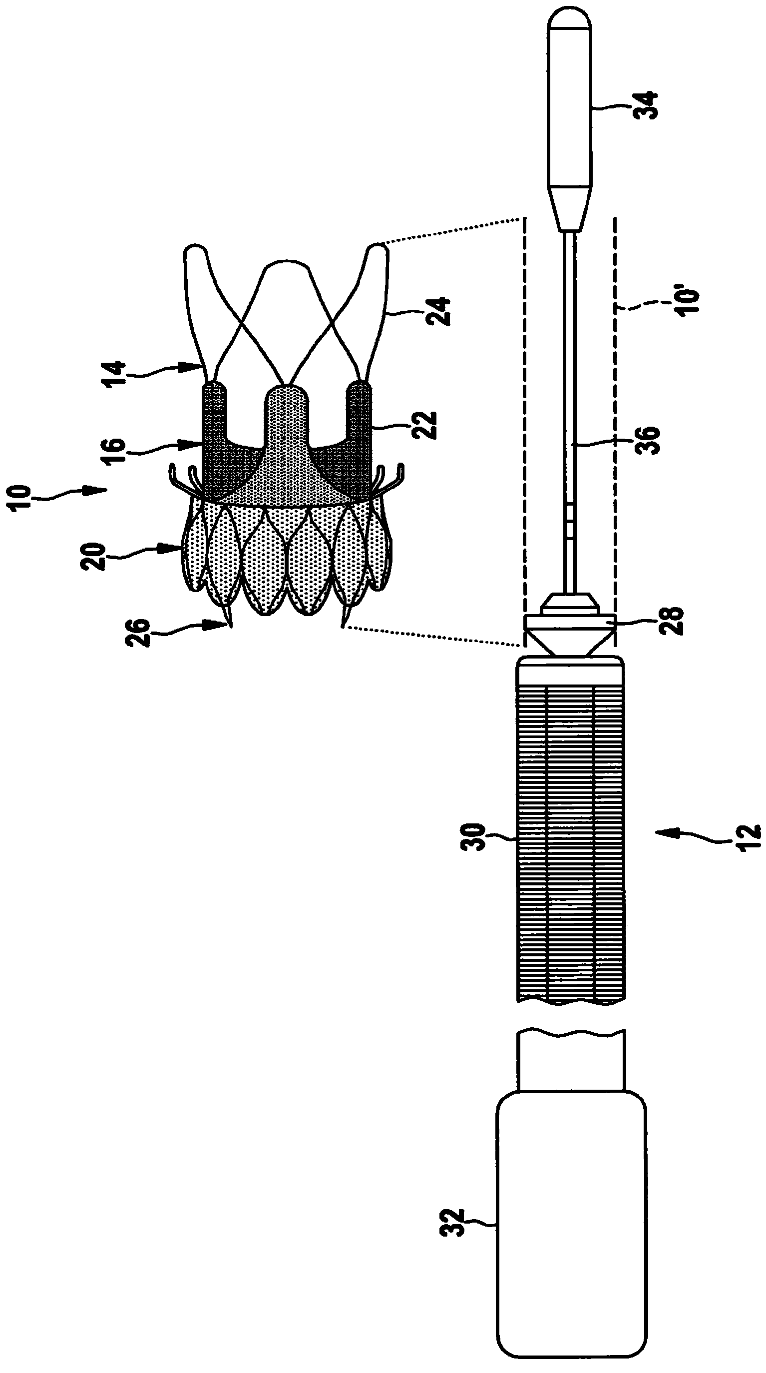
[0088] Before describing the compression device in detail, a stent (stent-valve) example is first described so that the characteristics and functions of the compression device will be fully understood.

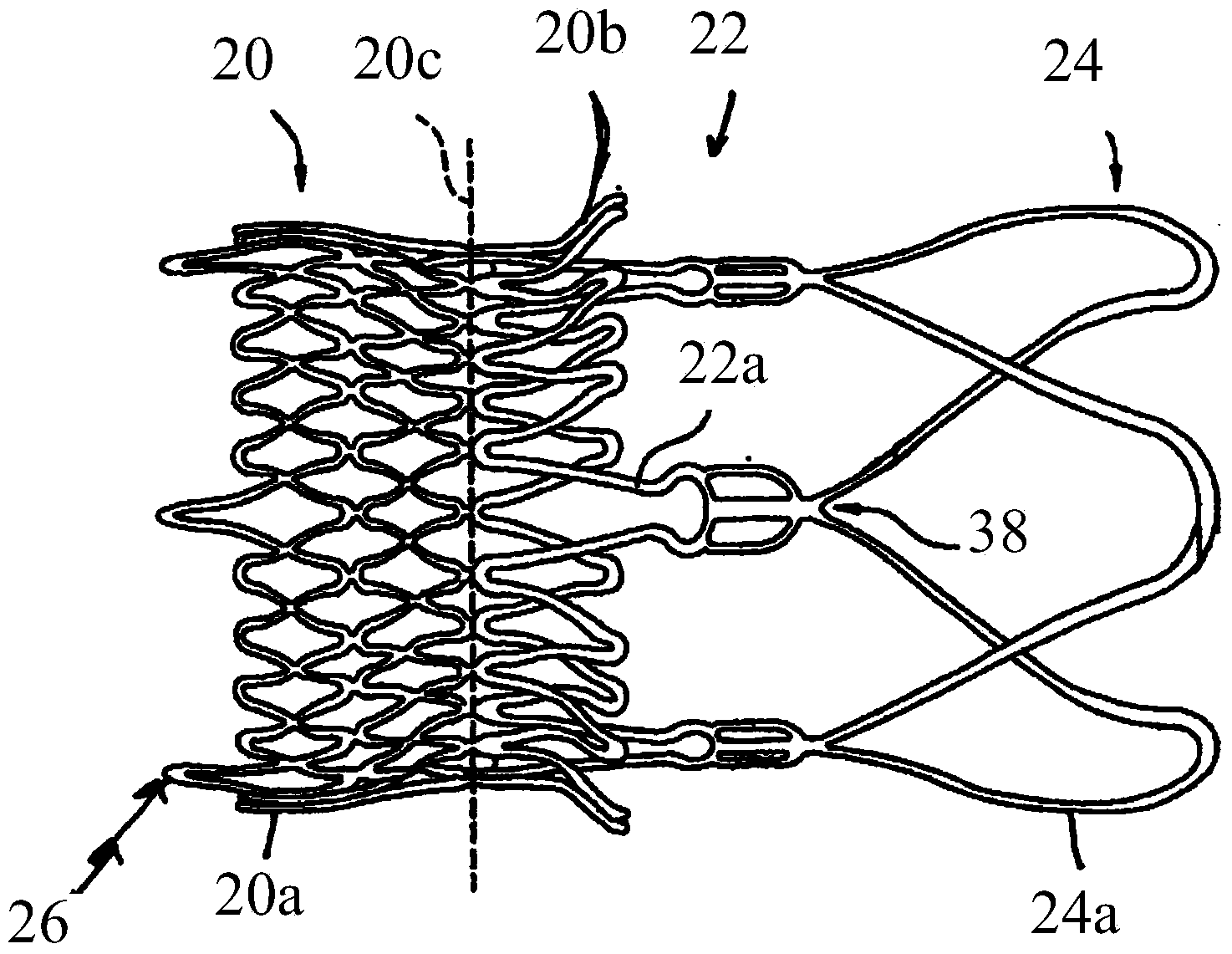
[0089] figure 1 and 2 An example of a stent in the form of a stent-valve 10 is shown. The stent-valve 10 may be an intracardiac stent-valve, such as an aortic stent-valve. Stent-valve 10 may be configured for transcatheter implantation in vivo, eg, to enable the use of minimally invasive techniques. Stent-valve 10 may be configured for transcatheter aortic valve implantation ("TAVI"). While a particular geometry of the stent-valve 10 is shown by way of example, it should be understood that the present invention is not limited to any particular stent-valve geometry. The geometry example used here is because it enables the advantages of the invention to be highlighted.

[0090] The stent valve 10 can be in an expanded state (such as figure 1 shown in ) and the compressed s...


PUM


Abstract

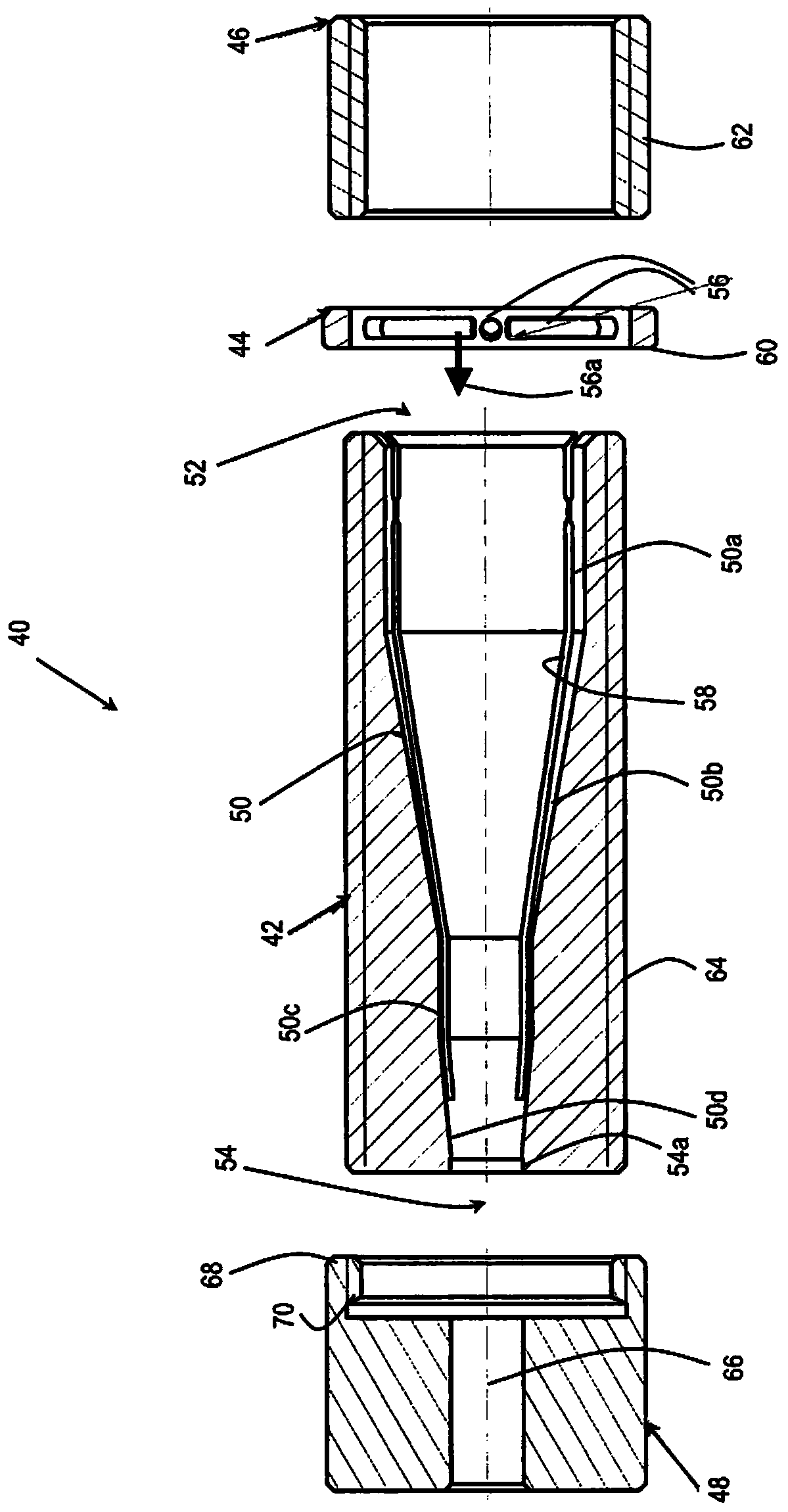
Apparatus (40) for compressing a transcatheter cardiac stent- valve (10) comprises: a hollow channel (42) having an interior surface (50) shaped for progressively compressing the stent- valve in response to longitudinal advancement of the stent-valve within the channel; a driver (46) threadedly engaged on the exterior of the channel for generating a longitudinal driving force in response to rotation; a mover (44) having limbs (56) that project through slots (58) in the channel wall to transmit the driving force to the stent-valve within the channel; and a channel extension (48) removably attachable at the exit (54) to provide a generally cylindrical containment bore (66).

Description

technical field [0001] The present invention relates to the field of stents for transcatheter delivery, and in particular to methods and apparatus for compressing a stent into a compressed state and / or for loading a stent for a delivery catheter. In some non-limiting aspects, the stent is a stent-valve, such as an intracardiac stent-valve. The present invention was designed while addressing the problems encountered with stent valves, but the present invention is also applicable to compressing other types of stents for transcatheter delivery. Background technique [0002] WO2009 / 053497A describes an intracardiac stent-valve and related methods and systems for delivering the stent-valve via minimally invasive procedures. The stent-valve is compressible to a compressed state suitable for placement on the delivery tip of the delivery catheter. In the compressed state, the small size enables the catheter carrying the stent-valve to be guided through minimally invasive procedure...

Claims


Application Information

Patent Timeline
IPC IPC(8): A61F2/24A61F2/95
CPCA61F2/0095A61F2/2412A61F2/2427A61F2/95A61F2/958A61F2250/0039A61F2/9525A61F2/9522A61F2/2418A61F2/2436A61B2050/005A61B2050/3014A61F2002/9505A61B2050/3008A61M25/002
Inventor J·艾辛格S·迪拉罗耶J-L·赫弗堤L·曼塔那斯M·帕里斯
Owner SYMETIS
Learn More