

Steel bar cutting machine
A steel bar cutting machine and cutting machine technology, applied in the direction of smoke removal, chemical instruments and methods, cleaning methods and utensils, etc., to achieve the effects of low manufacturing cost, improved working environment, and simple structure
- Summary
- Abstract
- Description
- Claims
- Application Information
AI Technical Summary
Problems solved by technology
Method used
Image

Examples
Embodiment Construction
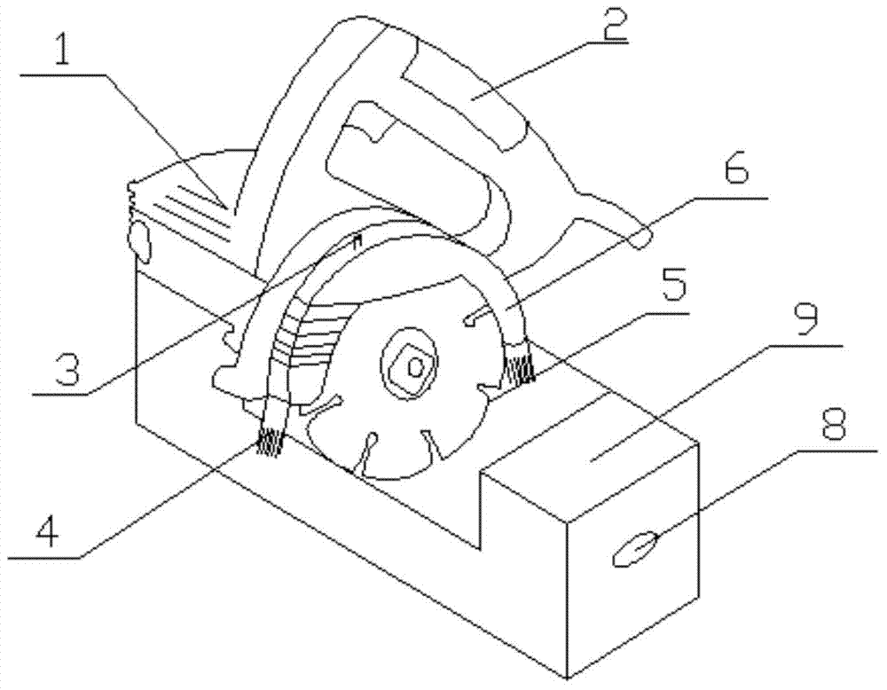
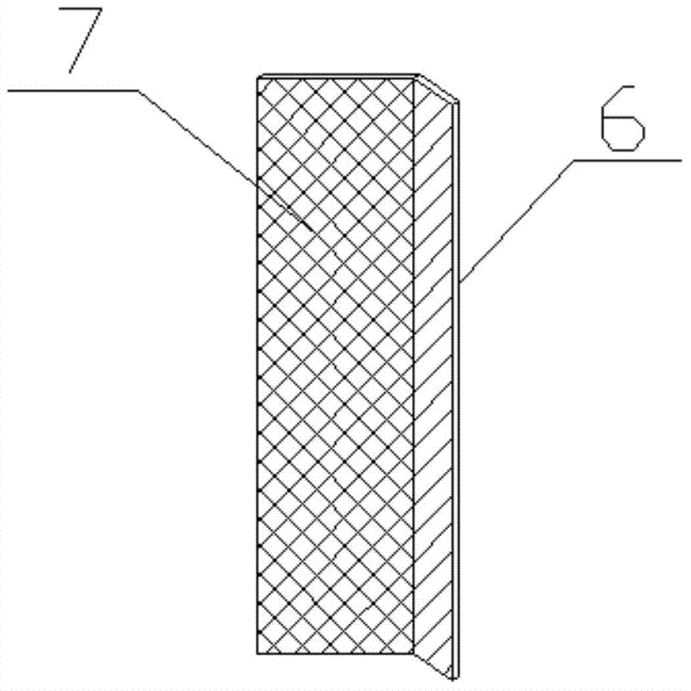
[0012] refer to figure 1 and figure 2 As shown, a steel bar cutting machine of the present invention includes a cutting machine body 1, a handle 2 arranged on the upper end of the cutting machine body 1, a protective cover 6 arranged on one side of the cutting machine body 1, and a protective cover 6 arranged on the side of the cutting machine body. The cutting blade 5 inside, and the workbench 9 arranged at the lower end of the cutting machine body 1, the workbench 9 is provided with a through hole 8, the upper end of the protective cover 6 is provided with a water injection port 3, and the protective cover 6 is provided with There is a water flow pipe, and a motor is arranged in the cutting machine body 1, and the motor is connected with the cutting blade 5, and the workbench 9 is detachably connected with the cutting machine body 1.
[0013] Pass the steel bar through the through hole 8, place it directly under the cutting blade 5, fix the position of the steel bar throug...
PUM
 Abstract
Description
Claims
Application Information