
Automatic pin punching equipment

An automatic punching and punching technology, applied in needles, other household appliances, household appliances, etc., can solve the problems of low efficiency, uneven product quality, and high labor costs, and achieve the effects of low cost, simple structure and high efficiency.

Inactive Publication Date: 2014-01-22
上海乾享机电科技有限公司
View PDF5 Cites 3 Cited by
  • Summary
  • Abstract
  • Description
  • Claims
  • Application Information

AI Technical Summary

Problems solved by technology

[0003] The traditional processing method of the above products is to manually punch metal needles from above the two block workpieces, which is inefficient, the product quality is uneven, and the labor cost is high

Method used


Image

  • Automatic pin punching equipment
  • Automatic pin punching equipment
  • Automatic pin punching equipment

Examples


Embodiment Construction

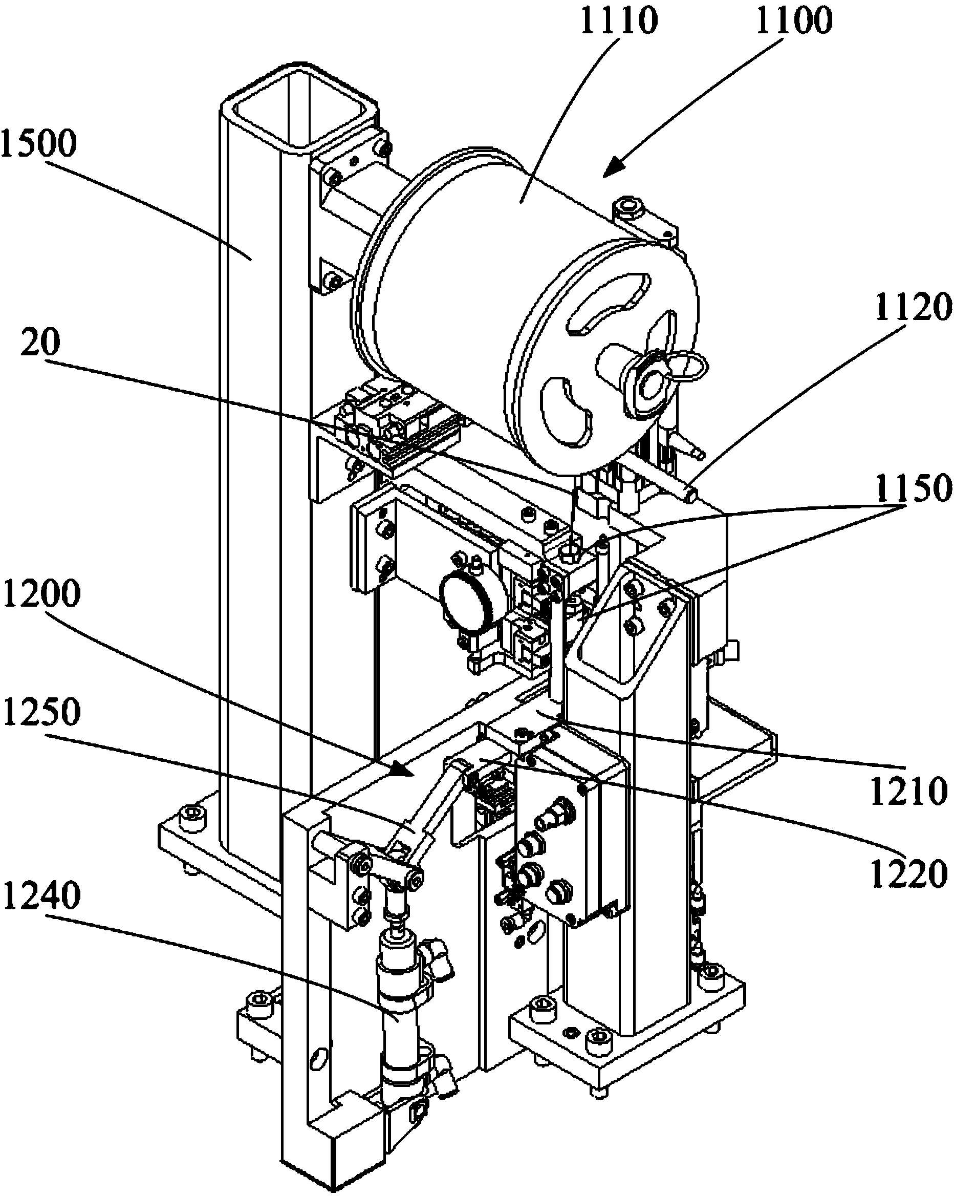
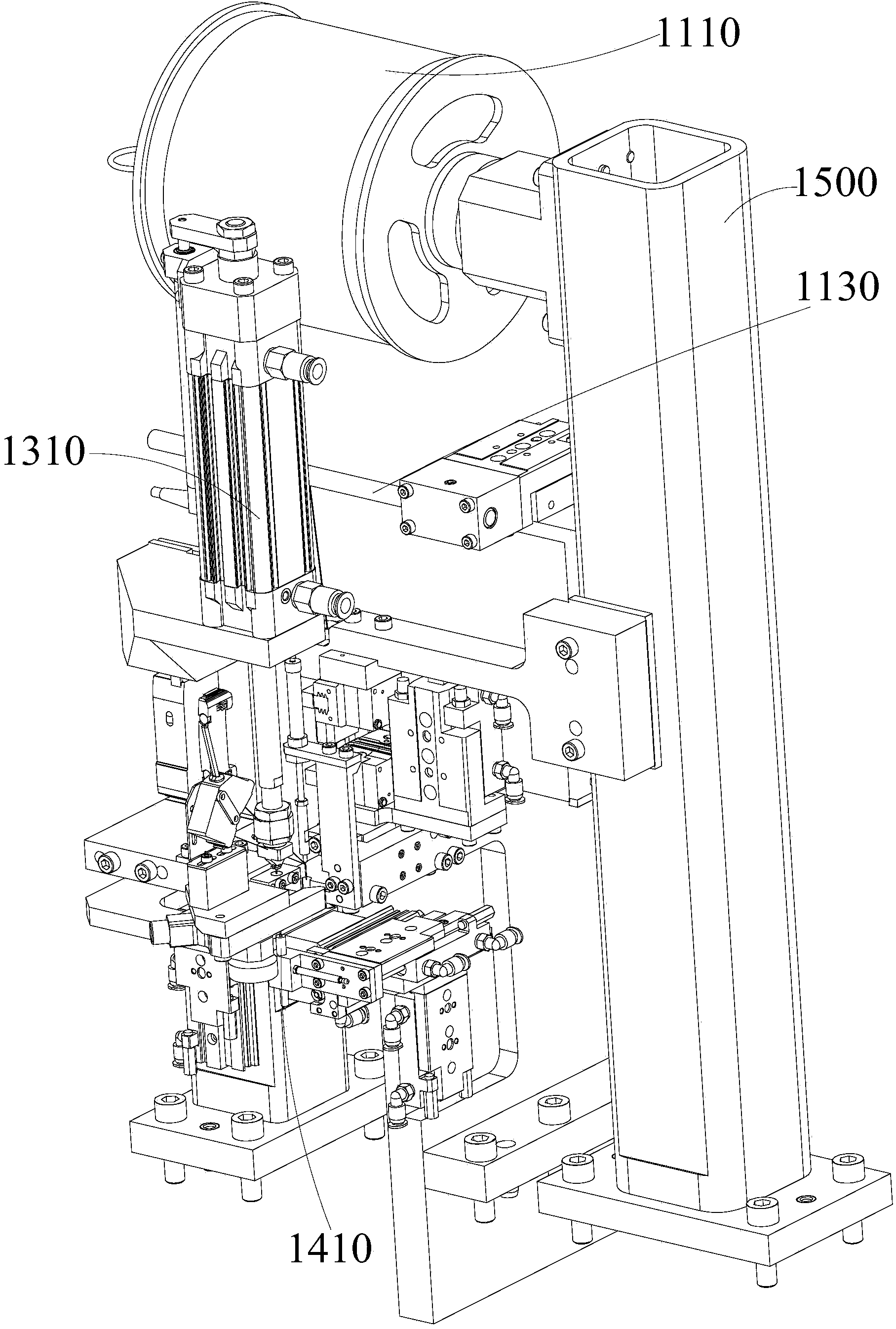
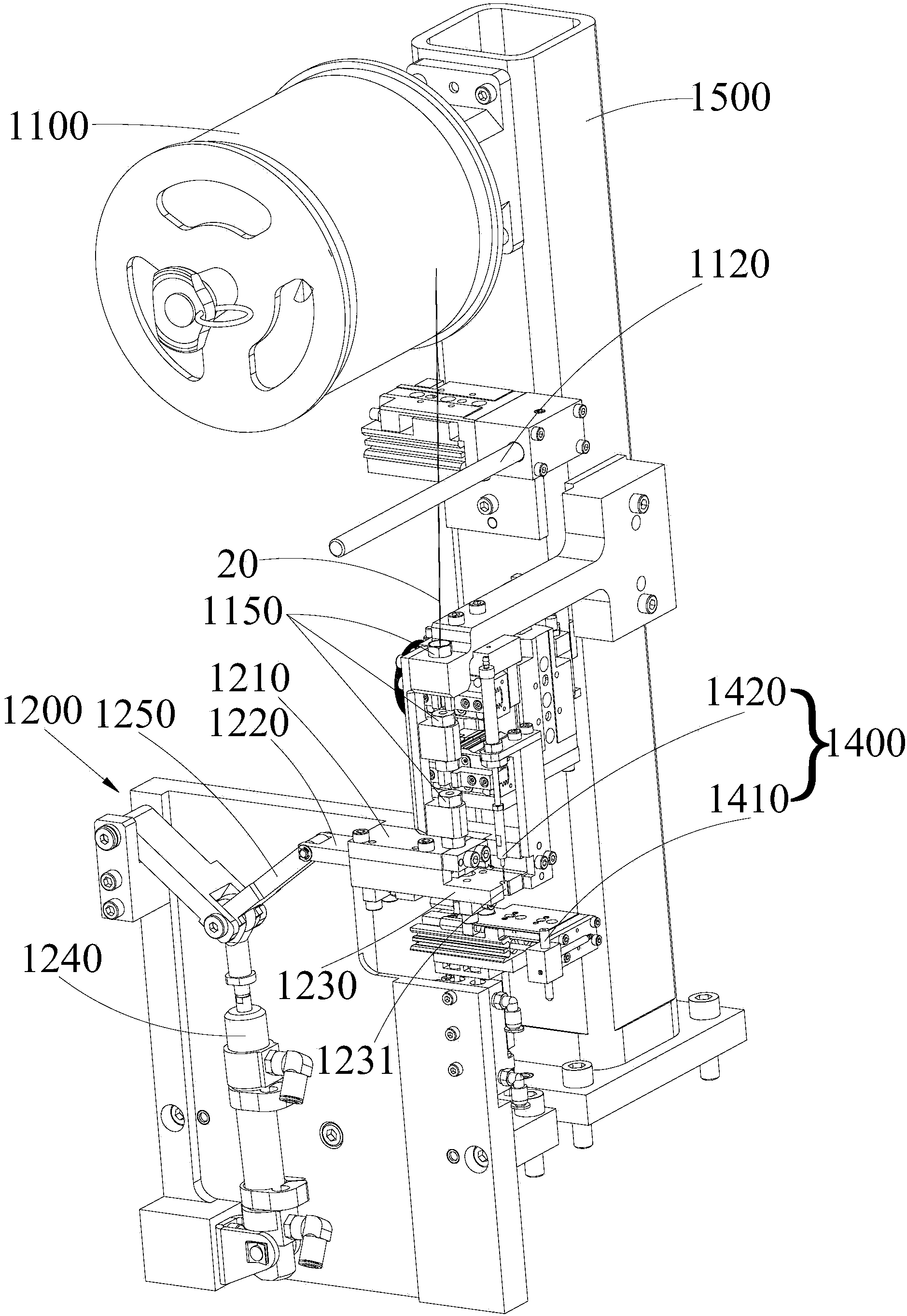
[0027] Such as Figure 1-3 as well as Figure 10 As shown, an automatic needle punching device includes a thread feeding mechanism 1100, a thread cutting mechanism 1200, a punching needle mechanism 1300 and a thread material transfer mechanism 1400, a thread feeding mechanism 1100, a thread cutting mechanism 1200, a needle punching mechanism 1300 and a thread material transfer mechanism 1400 All are arranged on the rack 1500.

[0028] Such as Figure 1-4 As shown, the wire feeding mechanism 1100 includes a wire feeding reel 1110 for conveying the metal wire 20, a tensioning rod 1120 located below the wire feeding reel 1110 and on the wire feeding path of the wire feeding reel 1110, a first wire clamp 1130 and a The second wire clamp 1140 moving axially along the metal wire 20, the first wire clamp 1130 and the second wire clamp 1140 are located below the tension rod 1120 at intervals in sequence. The first wire clamp 1130 performs a wire clamping action under the drive of a ...


PUM


Abstract

Automatic pin punching equipment comprises a wire feeding mechanism, a wire cutting mechanism, a pin punching mechanism and a wire transferring mechanism, wherein the wire feeding mechanism comprises a wire feeding plate, a tension rod, a first wire clamp and a second wire clamp, and the first wire clamp and the second wire clamp are located under the tension rod at an interval; the wire cutting mechanism comprises an upper wire cutting block, a lower wire cutting block and a wire cutting platform, the upper wire cutting block, the lower wire cutting block and the wire cutting platform are sequentially arranged under the wire feeding mechanism, the lower wire cutting block is arranged between the upper wire cutting block and the wire cutting platform in a sliding mode, the upper wire cutting block and the lower wire cutting block are respectively provided with a through hole, the through holes are communicated with each other, a notch is formed in the communicating portion of the two through holes, and the wire cutting platform is provided with a blanking hole at the finishing point of the sliding route of the lower wire cutting block; the pin punching mechanism comprises a pin punching cylinder, a punching pin and a pin punching platform; the wire transferring mechanism comprises a material collecting tube, a thimble and a moving device, the side faces of the material collecting tube are provided with blocking holes communicated with each other, a blocking needle is arranged in the blocking holes in a sliding mode, and the moving device is in transmission connection with the material collecting tube. According to the automatic pin punching equipment, automatic pin punching of products can be achieved, efficiency is relatively high, quality of the products is good, and cost is low.

Description

technical field [0001] The invention relates to automatic equipment, in particular to an automatic needle punching equipment. Background technique [0002] At present, a certain type of product on the market consists of two block-shaped workpieces and a metal needle. The metal needle is inserted in the two block-shaped workpieces from top to bottom in order to connect the two block-shaped workpieces into one. [0003] The traditional processing method of the above-mentioned products is to manually punch metal needles from the top of the two block workpieces, which is inefficient, the product quality is uneven, and the labor cost is high. Contents of the invention [0004] Based on this, aiming at the above technical problems, an automatic needle punching device is provided. [0005] In order to solve the problems of the technologies described above, the present invention adopts the following technical solutions: [0006] An automatic punching device, comprising: [0007...

Claims


Application Information

Patent Timeline
Patent Type & Authority Applications(China)
IPC IPC(8): B21F15/00B21F23/00B21F11/00B21G1/00
Inventor 高成艳
Owner 上海乾享机电科技有限公司
Learn More