
Welding tool for passenger car pivot rotating arms

A technology for welding tooling and passenger car doors, applied in welding equipment, auxiliary welding equipment, welding/cutting auxiliary equipment, etc. Improve assembly efficiency, improve accuracy, and ensure the effect of parallelism

Inactive Publication Date: 2014-01-22
HENAN LIANGYI MECHANICAL & ELECTRICAL +1
View PDF8 Cites 4 Cited by
  • Summary
  • Abstract
  • Description
  • Claims
  • Application Information

AI Technical Summary

Problems solved by technology

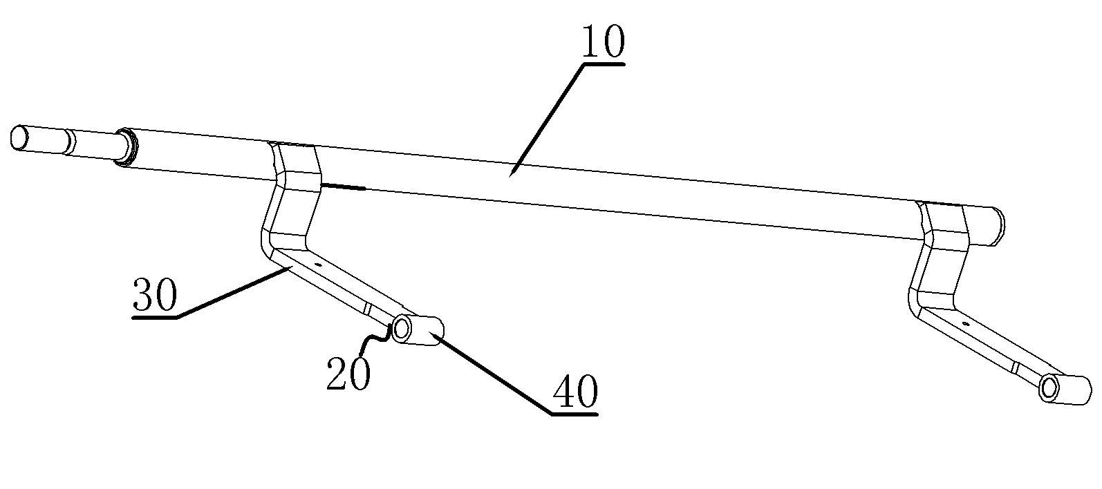
[0002] At present, the relative angles of the upper and lower swing arms on the door shaft in the door shaft assembly are debugged on site to ensure the normal switching action of the vehicle interior swing door, such as figure 1 The door shaft assembly shown includes a door shaft 10 and two rotating arms 20 welded on the door shaft, and each rotating arm 20 is welded by an L-shaped bent arm body 30 and the end of the bent arm body away from the door shaft 10 Rotary sleeve 40 constitutes, after this kind of rotating arm is manually welded on the door shaft 10, the concentricity error between the rotating sleeves on the two rotating arms is relatively large, so that after completing the assembly of the upper door part of the passenger car, The swing of the door panel does not match the predetermined trajectory, and even the door cannot complete the normal opening and closing action

Method used


Image

  • Welding tool for passenger car pivot rotating arms
  • Welding tool for passenger car pivot rotating arms
  • Welding tool for passenger car pivot rotating arms

Examples


Embodiment Construction

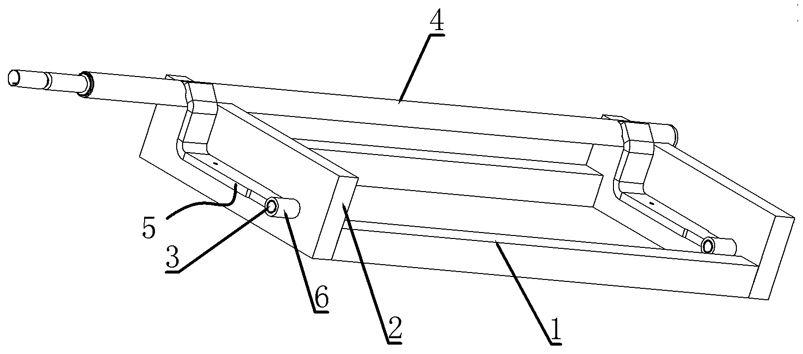
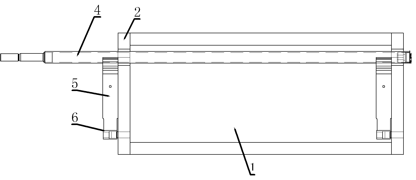
[0016] The embodiment of the passenger car door axle pivoting arm welding frock of the present invention: as Figure 2 to Figure 5 As shown, the tooling includes a base 1 and two positioning plates 2 fixed vertically and symmetrically on the left and right sides. The top surfaces of the two positioning plates 2 are respectively provided with door shaft locking grooves 21 extending along the same straight line extending left and right. The door shaft card slot 21 is a V-shaped slot with an opening facing upwards, and a positioning pin hole arranged parallel to the door shaft card slot 21 is opened on the left plate surface of the positioning plate 2, and a rotating sleeve is inserted in the positioning pin hole. Locating pin 3, the locating pin holes on the two locating plates 2 are coaxially arranged, so that the swivel locating pins 3 inserted in the two locating pin holes are coaxially arranged, and the axes of the two swivel locating pins 3 are aligned with the The extendin...


PUM


Abstract

The invention discloses a welding tool for passenger car pivot rotating arms. The welding tool for the passenger car pivot rotating arms comprises a base and two positioning plates which are vertically arranged on the base at intervals in a parallel mode. The top portions of the two positioning plates are respectively provided with a pivot clamping groove, wherein the pivot clamping grooves extend in the direction of the same horizontal straight line. The surfaces of the two positioning plates are provided with rotating sleeve positioning pins which are coaxially arranged, and the axes where the two rotating sleeve positioning pins are located are parallel to the extending direction of the straight line of the two pivot clamping grooves. When the welding tool is used, a pivot in a pivot assembly is limited in the radial direction and clamped into the pivot clamping grooves, rotating sleeves in the rotating arms are coaxially arranged on the rotating sleeve positioning pins in a sleeved mode, the rotating arms are rotated with the rotating sleeve positioning pins as the axis until the rotating arms are rotated to the position where the rotating arms are connected with the pivot, then the rotating arms are welded to the pivot, in the process, the coaxiality of the rotating sleeves of the two rotating arms can be guaranteed through the coaxially arranged rotating sleeve positioning pins, the parallelism of the rotating sleeves and the pivot can be guaranteed, and therefore the precision of assembling the whole pivot assembly is improved.

Description

technical field [0001] The invention relates to a welding tool for a door shaft rotating arm of a passenger car. Background technique [0002] At present, the relative angles of the upper and lower swing arms on the door shaft in the door shaft assembly are debugged on site to ensure the normal switching action of the vehicle interior swing door, such as figure 1 The door shaft assembly shown includes a door shaft 10 and two rotating arms 20 welded on the door shaft, and each rotating arm 20 is welded by an L-shaped bent arm body 30 and the end of the bent arm body away from the door shaft 10 Rotary sleeve 40 constitutes, after this kind of rotating arm is manually welded on the door shaft 10, the concentricity error between the rotating sleeves on the two rotating arms is relatively large, so that after completing the assembly of the upper door part of the passenger car, The swing of the door panel does not match the predetermined trajectory, and even the door cannot compl...

Claims


Application Information

Patent Timeline
Patent Type & Authority Applications(China)
IPC IPC(8): B23K37/04
CPCB23K37/0426B23K2101/006
Inventor 许军委
Owner HENAN LIANGYI MECHANICAL & ELECTRICAL
Learn More