Method for connecting filter drum and built-in filter liner of water purifier in rotary inserting and rotary lifting manner, and built-in filter liner

A technology of water purifier and plug-in connection, which is applied in chemical instruments and methods, multi-stage water/sewage treatment, water/sludge/sewage treatment, etc. It is difficult to popularize the device more widely, and the axial size is difficult to operate, so as to achieve the effect of simple and fast connection or separation operation, avoiding inconvenience and service expenses, and light weight

Active Publication Date: 2014-01-22
杜也兵
View PDF5 Cites 15 Cited by
  • Summary
  • Abstract
  • Description
  • Claims
  • Application Information

AI Technical Summary

Problems solved by technology

However, because the axial dimension of the built-in filter gall is smaller than that of the filter cartridge, it is also very difficult to operate.
In addition, it is difficult to design the water purifier as a multi-filter system with more than three filter cartridges in the space under the cabinet sink where the width is less than 20 centimeters, the length is less than 55 centimeters, and the height is less than 45 centimeters. Barrel structure
The related problems caused by replacing the filter gallbladder often appear repeatedly, so that it is recognized as one of the three major problems that water purifiers are difficult to popularize
Above-mentioned defect and deficiency cause water purifier to be difficult to obtain wider popularization

Method used


Image

  • Method for connecting filter drum and built-in filter liner of water purifier in rotary inserting and rotary lifting manner, and built-in filter liner
  • Method for connecting filter drum and built-in filter liner of water purifier in rotary inserting and rotary lifting manner, and built-in filter liner
  • Method for connecting filter drum and built-in filter liner of water purifier in rotary inserting and rotary lifting manner, and built-in filter liner

Examples


Embodiment 1

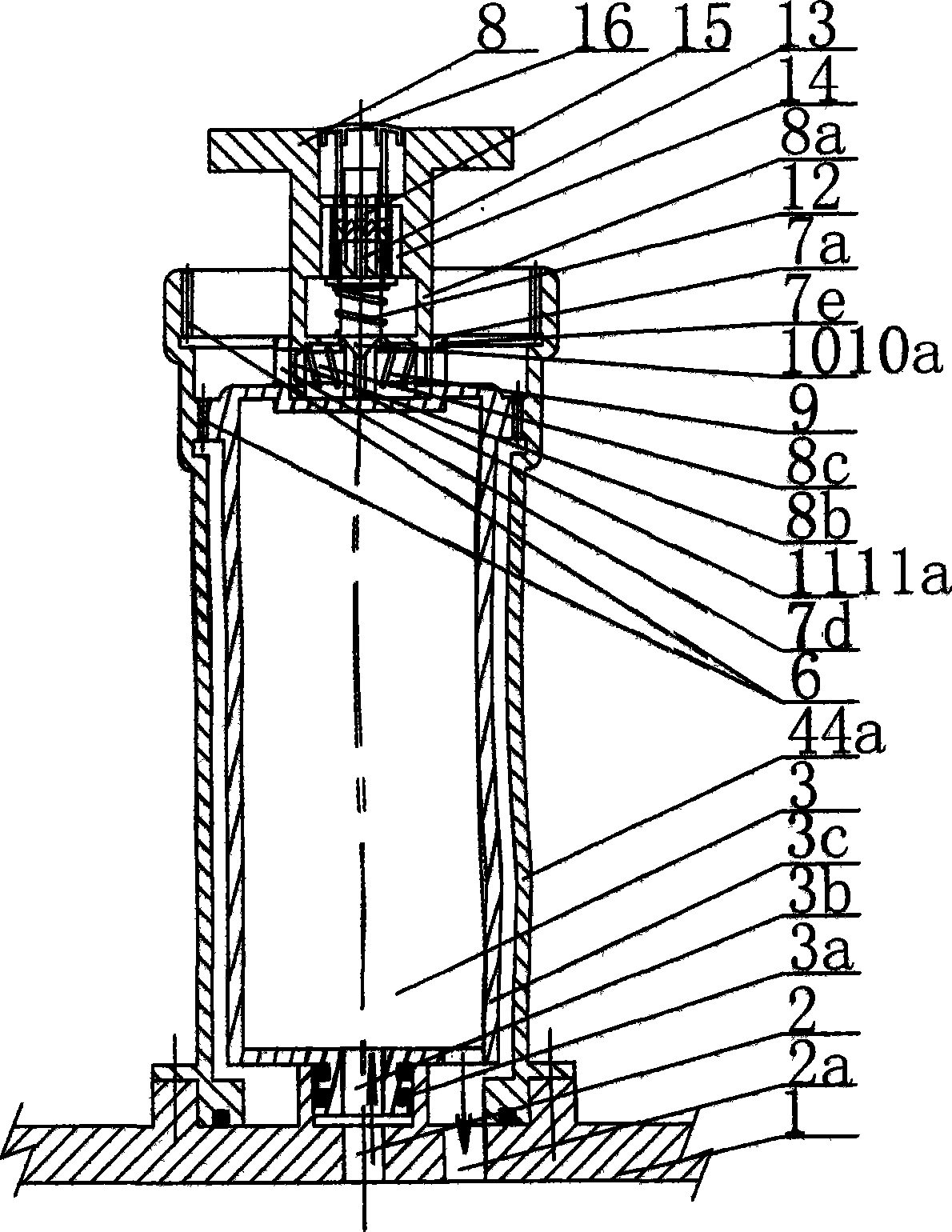
[0036] Example 1. figure 1 , 2 A preferred embodiment of the invention is shown.

[0037] When plugging in the built-in closed filter gall 3, the polygonal plug-in structure 7a provided on the lower bracket 8a of the handle mechanism 8 and the polygonal plug-in structure 7a of the externally convex member 7e of the built-in closed filter gall 3 are inserted into each other, and the radial holes of the two parts 7d and 8b also correspond to each other. Press the button 16 located in the center of the handle mechanism 8 to make the position switching gear lever 15 move downward along the axial guide groove of the one-way ratchet outer cover 14 fixed on the bracket 8a, and push the one-way ratchet which is in the incomplete engagement state f The swivel 13 also moves downwards accordingly until its ratchet tooth tip is completely engaged when it is lower than the lower end of the one-way ratchet overcoat 14: under the action of the upward rebound force of the locking spring 12,...

Embodiment 2

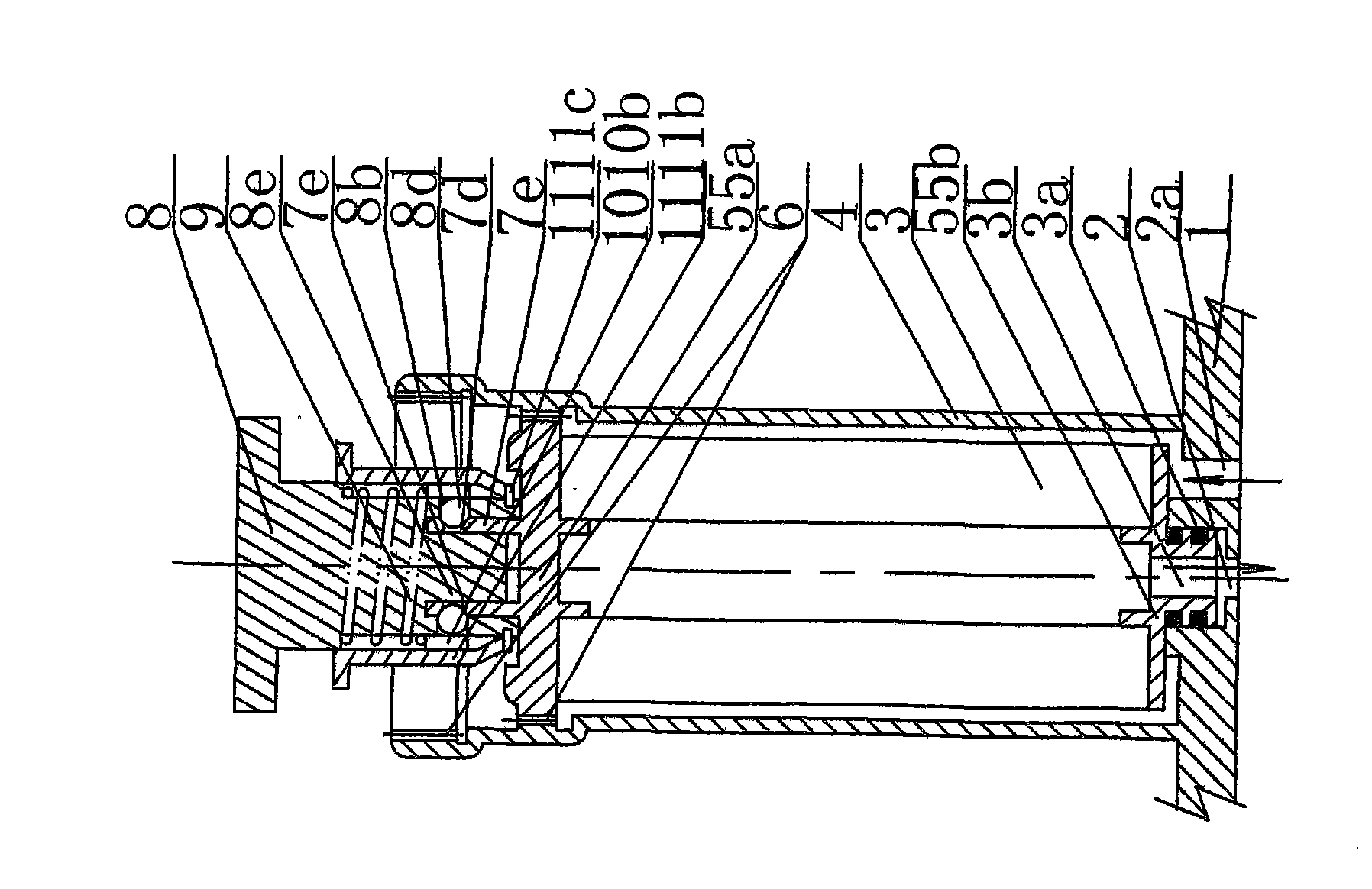
[0045] Example 2. image 3 A second embodiment of the invention is shown.

[0046] exist image 3 On the basis of the structure, when the built-in bare bladder 3 is plugged in, the limit sleeve 11b as the handle mechanism limiter 11 is pulled up, and the polygonal insertion structure 7a provided on the lower bracket 8e of the handle mechanism 8 is connected to the outside of the built-in bare bladder 3. The polygonal insertion structures 7a of the male member 7e are inserted into each other, and the radial holes 7d and 8b of the two parts also correspond to each other. The front end of the ball 8d located in the through hole 8b on the wall of the lower bracket 8e is pushed into the through hole of the lower bracket 8e when it encounters the protruding member 7e of the built-in bare bladder 3, and its rear end moves outward to the lower end of the push sleeve 10b and The reset position in the groove between the limit sleeves 11b. At this time, the handle mechanism 8 and the ...

Embodiment 3

[0050] Example 3. Figure 4 A third embodiment of the present invention is shown.

[0051] Figure 4 Among them, the one-piece filter cartridge 4 and the built-in bare tank 3 are connected and screwed together by a screw screw structure 6 . The top surface of the upper end cover 5a of the built-in bare bladder 3 is provided with an outwardly protruding member 7f with a threaded connection structure 7g. The lower bracket 8f of the handle mechanism 8 and the built-in naked bladder 3 are inserted into each other with the polygonal plug-in structure 7a. The handle mechanism 8 is also provided with a threaded connection piece 8g connected to the built-in bare bladder 3 threaded connection structure 7g. The threaded connector 8g is sleeved on the lower support 8f and can move up and down. The lower bracket 8f is inserted into the handle mechanism 8 and connected by a pin 8h to form a single body.

[0052] When inserting the built-in closed filter gallbladder 3, the polygonal pl...


PUM


Abstract

The invention relates to water treatment industry, in particular relates to the depth-type filtration and purification of drinking water, and discloses a method for connecting a filter drum and a built-in filter liner of a water purifier in a rotary inserting and rotary lifting manner, and the built-in filter liner. A convex insertion water opening with a sealing component is arranged at the lower end of the built-in filter liner positioned in a sealing cavity of the filter drum and is matched with a water passing hole of the built-in filter liner in an inserting manner; the rotary threaded inserting structure is arranged along the peripheral surface of the built-in filter liner or positioned on the peripheral surface of a casing of the built-in filter liner or positioned on the peripheral surface of the end cover of the built-in filter liner; a corresponding rotary threaded inserting structure matched with the built-in filter liner in a rotary connecting manner is arranged on the inner wall of the filter drum; the built-in filter liner positioned at high and low inserting and connecting positions can automatically move downwards or upwards when rotating along positive and negative directions of the rotary threaded inserting structures; the convex insertion water opening with the sealing component and the pipe wall of the water passing hole of a base are inserted together in a sealing manner or separated from each other; a linkage matching state and a separation matching state are set between a handle mechanism axially or rotatably linked with the built-in filter liner and a rotary lifting structure of the built-in filter liner.

Description

technical field [0001] The invention relates to the water treatment industry, and specifically relates to the deep filtration and purification of drinking water. Background technique [0002] At present, water purifiers are relatively popular in China. When drinking water is used, the water purifier is used to deeply filter the impurities in the water and water pipelines, which better protects the health of users. Yet, along with the popularization of water purifier, their defect and deficiency also gradually exposed in application aspect. After the filter gall of the water purifier is used for a period of time, the filter material of the filter gall is gradually blocked by impurities and adsorbed on the outer surface of the filter material, resulting in a significant decline in the filtering and adsorption effects. As more and more impurities are retained by the filter gall, the filter gall will often become a new source of "pollution", and the filter gall must be replace...

Claims


Application Information

Patent Timeline
Patent Type & Authority Applications(China)
IPC IPC(8): C02F9/02
Inventor 杜也兵冉伊虹
Owner 杜也兵
Why Eureka
Try Eureka