

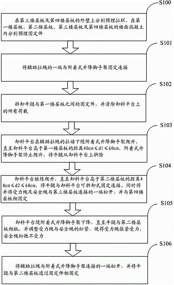
An overall lifting method for unloading platform
An unloading platform and overall lifting technology, applied in the processing of building materials, construction, building structure, etc., can solve the problems that the unloading platform cannot be accurately lifted, occupying space, affecting construction, etc., and achieves rapid lifting and installation. , improve utilization efficiency, improve the effect of improving efficiency
- Summary
- Abstract
- Description
- Claims
- Application Information
AI Technical Summary
Problems solved by technology
Method used
Image

Examples
Embodiment Construction
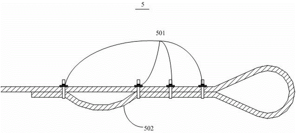
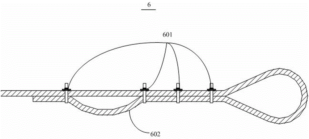
[0032] Please also refer to figure 1 , Figure 7 and Figure 11 , the present invention provides an overall lifting method for the unloading platform. The unloading platform 1 is detachably fixedly connected with one end of the corbel 2, and the other end of the corbel 2 is anchored and fixed with the main structure 3 through the fixing part 4, and the force The rope 5 and the safety rope 6 are connected to the unloading platform 1 and the main structure 3, the auxiliary pull rope 7 is connected to the unloading platform 1 and the attached lifting scaffold (not shown in the figure), and the outer wall of the floor plate of the main structure 3 is embedded with a pull Ring 8, ring 9 is fixed on the unloading platform 1. The unloading platform 1 includes a base 101 and a guardrail 102 arranged on the base 101. The base 101 includes a main beam 101a, a secondary beam 101b, a scaffold board 101c and an overhanging net frame 101d. There are two main beams 101a, and one end of the...
PUM
 Abstract
Description
Claims
Application Information