Method for controlling valve timing of diesel engine

A control method, diesel engine technology, applied in the direction of engine control, mechanical equipment, engine components, etc., can solve the problems of different personal feel, many process parts, high cost, etc., and achieve the effect of accurate control, high precision, and simple operation of the detection process

Active Publication Date: 2014-01-22
WEICHAI HEAVY MACHINERY
View PDF6 Cites 5 Cited by
  • Summary
  • Abstract
  • Description
  • Claims
  • Application Information

AI Technical Summary

Problems solved by technology

[0006] Using the above control method, the valve timing can be obtained relatively simply. However, the above control method relies on the operator's feeling to know whether there is resistance or resistance disappears, and personal feel is different, especially for large diesel engines with relatively large valve tim...

Method used


Image

  • Method for controlling valve timing of diesel engine

Examples


Embodiment Construction

[0027] The core of the present invention is to provide a method for controlling the valve timing of a diesel engine, which can accurately measure the valve timing of a large-scale four-stroke diesel engine, further enhance the accuracy of control, and has a lower cost.

[0028] In order to enable those skilled in the art to better understand the technical solutions of the present invention, the present invention will be further described in detail below in conjunction with the accompanying drawings and specific embodiments.

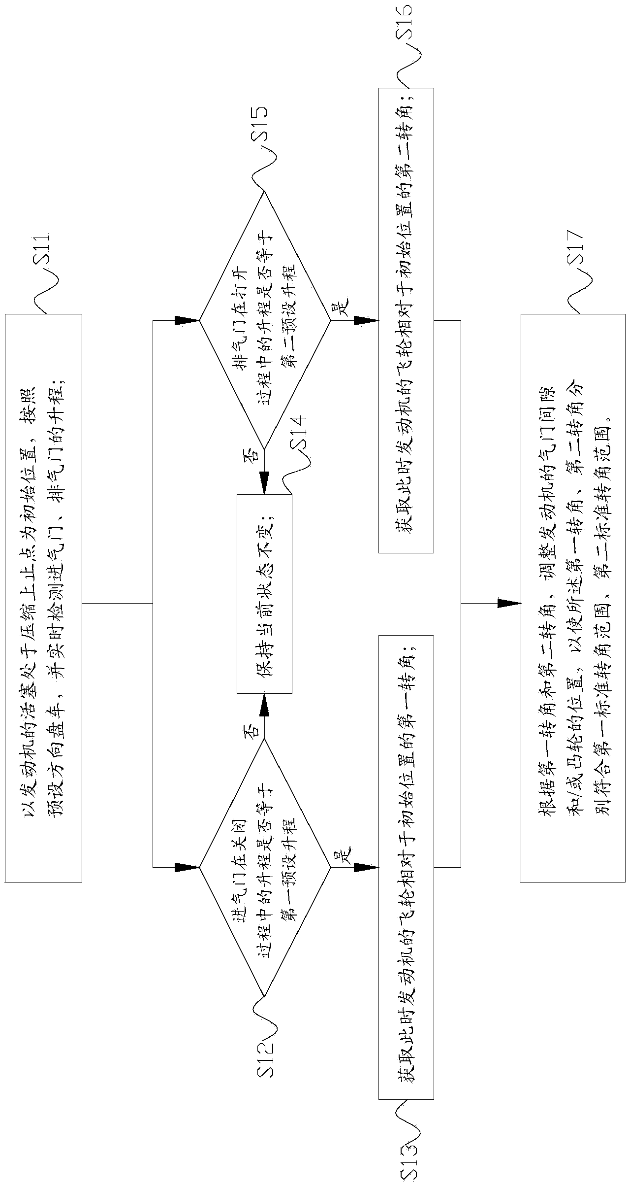
[0029] Please refer to figure 1 , figure 1 It is a block flow diagram of a specific embodiment of the valve timing control method provided by the present invention.

[0030] In a specific embodiment, such as figure 1 As shown, the present invention provides a method for controlling valve timing, which mainly includes the following steps:

[0031] S11: With the piston of the engine at the compression top dead center as the initial position, drive accord...


PUM

PropertyMeasurementUnit
Corneraaaaaaaaaa

Abstract

The invention discloses a method for controlling valve timing of a diesel engine. The method comprises the steps of barring the engine in a preset direction with the position where a piston is on a top dead center of compression as the initial position and detecting the lifting ranges of an inlet valve and an exhaust valve in real time; acquiring a first corner, relative to the initial position, of a flywheel of the engine at the moment when the lifting range, during closing, of the inlet valve is equal to a first preset lifting range; acquiring a second corner, relative to the initial position, of the flywheel at the moment when the lifting range, during opening, of the exhaust valve is equal to a second preset lifting range; adjusting the valve clearance and/or the position of a cam of the engine according to the first corner and the second corner to enable the first corner and the second corner to conform with a first standard corner range and a second standard corner range respectively. According to the method for controlling valve timing of the diesel engine, the corners corresponding the preset lifting ranges of the valves serve as reference values of valve timing to detect whether valve timing meets requirements accurately, adjustment is carried out in a targeted mode, and then technological requirements of the valve timing are finally met.

Description

technical field [0001] The invention relates to the technical field of engines, in particular to a method for controlling valve timing of a diesel engine. Background technique [0002] As we all know, in the actual working process of a diesel engine, the opening and closing of the intake valve and the exhaust valve are not at the position where the piston is at the top dead center or the bottom dead center, but must be opened in advance and closed with a delay to achieve the maximum possible intake air. The purpose of full, exhaust as clean as possible. Use the crankshaft angle to represent the opening and closing moments of the intake valve and exhaust valve, which is called valve timing. Each type of diesel engine has its own valve timing, which are generally determined through experiments during design. Valve timing It can be represented by a valve timing diagram. [0003] At present, the detection method of valve timing in the assembly process of diesel engine includes...

Claims


Application Information

Patent Timeline
IPC IPC(8): F01L1/344F02D13/02
Inventor 赵伟李雷
Owner WEICHAI HEAVY MACHINERY
Why Eureka
Try Eureka