Centrifugal pump
A centrifugal pump and vane technology, applied in the field of centrifugal pumps, can solve the problems of high manufacturing and maintenance costs, short service life of the impeller, etc., and achieve the effects of improving the service life, saving the overall cost, and diversifying the fixing methods.
- Summary
- Abstract
- Description
- Claims
- Application Information
AI Technical Summary
Problems solved by technology
Method used
Image
Examples
Embodiment 1
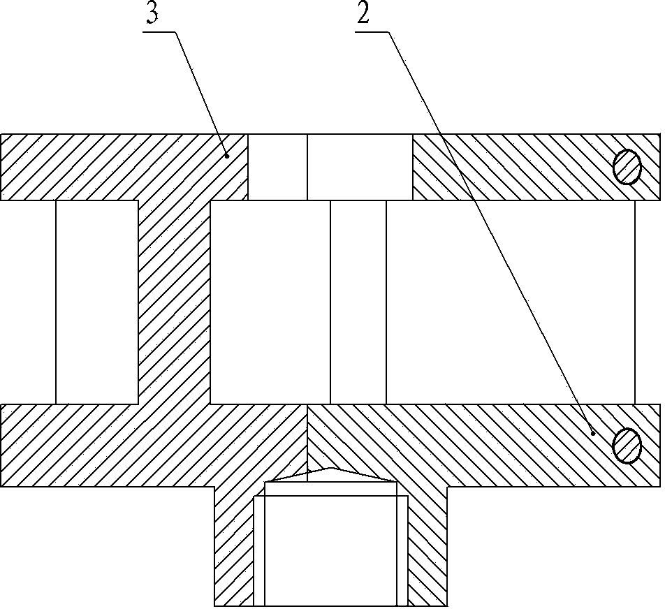
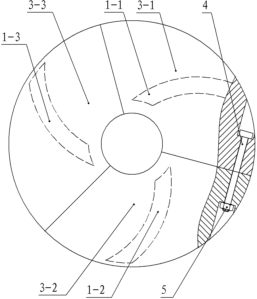
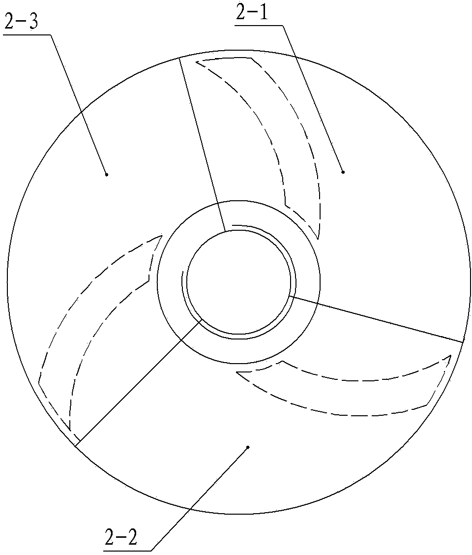
[0026] Embodiment 1: Enclosed impeller (including blade 1, front cover 3 and rear cover 2)
[0027] Such as Figure 1~Figure 3 The shown centrifugal pump includes an impeller, and the impeller is divided into three connecting blocks with the same shape. The first block is a connecting block composed of a blade part 1-1, a front cover part 3-1 and a rear cover part 2-1. The second block is a connection block composed of the blade part 1-2, the front cover part 3-2 and the rear cover part 2-2, and the third block is composed of the blade part 1-3, the front cover part 3-3 and the The connecting blocks formed by the back cover parts 2-3, the back cover parts 2-1, 2-2, 2-3 of each connecting block are spliced into a circular plate body on the side where the blade part is connected to the drive shaft; The front cover parts 3-1, 3-2, and 3-3 of the connecting blocks are spliced into a circular plate body located on the opposite side of the connecting drive shaft on the blade pa...
Embodiment 2
[0028] Embodiment 2: Enclosed impeller (including blade 1, front cover 3 and rear cover 2)
[0029] Such as Figure 1~Figure 3 In the centrifugal pump shown, the structure of the impeller is the same as in the first embodiment, and the surface of the blade 1 is inlaid with a wear-resistant material with a hardness greater than or equal to HRC50; the wear-resistant material is a hard alloy material.
Embodiment 3
[0030] Embodiment 3: front semi-open impeller (including blade 11, rear cover 12)
[0031] Such as Figure 4~Figure 5 The shown centrifugal pump includes an impeller, and the impeller is divided into three pieces with the same shape. The first piece is a connection block composed of the blade part 11-1 and the rear cover plate part 12-1, and the second piece is made of the blade part 11-2. and the connecting block composed of the rear cover part 12-2, the third piece is a connecting block composed of the blade part 11-3 and the rear cover part 12-3, the rear cover parts 12-1, 12- of each connecting block 2. 12-3 is spliced into a circular plate on the side where the blade part is connected to the drive shaft, and the connecting blocks are connected by bolts 4 and nuts 15; the blade 11 is made of a wear-resistant material with a hardness greater than or equal to HRC50. The wear-resistant material is ceramic material.
PUM
 Abstract
Description
Claims
Application Information
 - R&D
- Intellectual Property
- Life Sciences
- Materials
- Tech Scout
- Unparalleled Data Quality
- Higher Quality Content
- 60% Fewer Hallucinations
Browse by: Latest US Patents, China's latest patents, Technical Efficacy Thesaurus, Application Domain, Technology Topic, Popular Technical Reports.
© 2025 PatSnap. All rights reserved.Legal|Privacy policy|Modern Slavery Act Transparency Statement|Sitemap|About US| Contact US: help@patsnap.com


