Power takeoff

A technology of power take-off and clutch, applied in the direction of magnetic drive clutch, clutch, fluid drive clutch, etc., to achieve the effect of increasing the effective area, ingenious structure and reducing random rotation

Inactive Publication Date: 2014-01-22
西安双特智能传动有限公司
View PDF5 Cites 9 Cited by
  • Summary
  • Abstract
  • Description
  • Claims
  • Application Information

AI Technical Summary

Problems solved by technology

For the power source with automatic transmission that is more and more widely used at present, there is no power take-off that can match it in the prior art

Method used


Image

  • Power takeoff
  • Power takeoff
  • Power takeoff

Examples


Embodiment Construction

[0029] The present invention will be further described in detail below in conjunction with specific embodiments, which are explanations of the present invention rather than limitations.

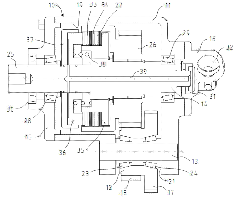
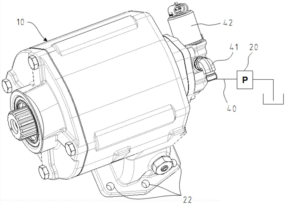
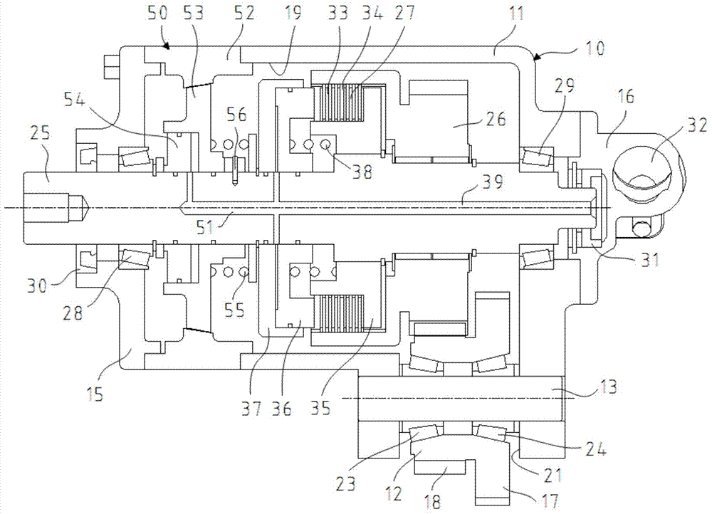
[0030] A kind of power take-off of the present invention, as figure 1 and figure 2 As shown, it includes a housing 11 provided with an inner chamber 19 and an opening 21, an output shaft assembly 14 arranged in the inner chamber 19, an input gear 12 installed in the opening 21, and a device for providing control power for the output shaft assembly 14. Oil supply system; the output shaft assembly 14 cooperates with the input gear 12 to realize the power absorption of the attachment device to the power source, that is, the input gear 12 extracts power from the power source, and after transmission, the output shaft assembly 14 transmits it to the attachment device. Complete power delivery and absorption extraction.

[0031] Wherein, output shaft assembly 14 comprises output shaft 25, output g...


PUM


Abstract

The invention discloses a power takeoff which comprises a shell, an output shaft assembly, an input gear and an oil supply system, wherein the shell is provided with an inner cavity and an opening, the output shaft assembly is arranged in the inner cavity, and the input gear is mounted in the opening. The output shaft assembly is matched with the input gear, so that an accessory device absorbs power of a power source, the output shaft assembly comprises an output shaft, output gears and clutches, the output gears are rotatably mounted on the output shaft, each clutch comprises dual discs, a clutch piston, friction discs, a clutch piston seat and a compression reset spring, the dual discs and the output gears are fixed, the clutch pistons, the friction discs and the output shaft are radially fixed and jointly act, the clutch piston seats and the output shaft are fixed, a valve seat connected with the oil supply system is arranged at one end of the shell, a bearing cover is arranged at the other end of the shell, an input end of the output shaft is connected with the shell and communicated with the oil supply system through an oil channel arranged inside the output shaft, and an oil outlet end of the oil channel is communicated with clutch cavities among the clutch pistons and the clutch piston seats. When the clutch cavities feed and drain oil, the clutches are correspondingly combined and separated, and the friction discs and the dual discs correspondingly transmit in a compressed manner and freely rotate.

Description

technical field [0001] The invention relates to a power transmission device capable of taking power or power from a power source and delivering it to an accessory device that needs to be driven, specifically a power take-off. Background technique [0002] A power take-off is typically used with a power source such as an automotive engine, electric motor or transmission to provide drive power to an accessory device. For example, power take-offs are used on both on-highway and off-highway vehicles to provide power to accessory devices such as oil pumps, water pumps, motors, compressors, articulating discs, fans, etc. Provide power to oil pumps and various accessories on industrial equipment. Provide power to lawn mowers and hoists on agricultural vehicles. Provide power to oil pumps, propulsion devices, etc. on marine vehicles. [0003] A typical power take-off consists of a casing, an input gear extending outside the casing, and an output shaft extending outside the casing...

Claims


Application Information

Patent Timeline
Patent Type & Authority Applications(China)
IPC IPC(8): F16D25/12F16D27/10
Inventor 王军柯瓦泽王亚锋周能文李军田野毕乾坤
Owner 西安双特智能传动有限公司
Why Eureka
Try Eureka