Gear of textile machine

A machine gear and textile technology, applied in belts/chains/gears, mechanical equipment, engine components, etc., can solve the problems of uneven distribution of lubricating oil, easy local damage, easy wear of helical teeth, etc., to save materials, Extends service life and avoids the effect of insufficient stiffness

Inactive Publication Date: 2014-01-22
CHANGSHU FANGYUAN TEXTILE EQUIP FACTORY
View PDF7 Cites 3 Cited by
  • Summary
  • Abstract
  • Description
  • Claims
  • Application Information

AI Technical Summary

Problems solved by technology

[0002] Entering the 21st century, the world is constantly developing. my country's textile industry has also made great progress during this period, including the field of textile machinery and equipment. With the development of science and technology, people have put forward higher requirements for product quality. requirements, the application number is CN201220155826.1 discloses a textile machine gear, including the gear sleeve and the gear hub, the gear sleeve and the gear hub are integrally processed, and the two sides are flush, the gear hub peripheral only A circle of gear ring, the gear ring and the gear hub are integrally processed, the gear ring is composed of several helical teeth arranged on the peripheral surface of the gear hub, and the inner wall of the gear sleeve is provided with key grooves, the gear can be effectively Material saving and rational use of materials greatly save material waste and resource consumption, and can save costs, improve efficiency, and effectively promote development. Helical teeth replace traditional straight teeth and improve the running performance of textile machine gears, but When the staff lubricates the gears, the lubricating oil is not easy to be evenly distributed to each helical tooth, resulting in unsatisfactory lubrication effect and easy local damage, and the helical teeth of the gear are prone to wear during long-term work, resulting in gear damage , reducing its useful life

Method used


Image

  • Gear of textile machine
  • Gear of textile machine
  • Gear of textile machine

Examples


Embodiment Construction

[0013] In order to make the technical means, creative features, goals and effects achieved by the present invention easy to understand, the present invention will be further described below in conjunction with specific embodiments.

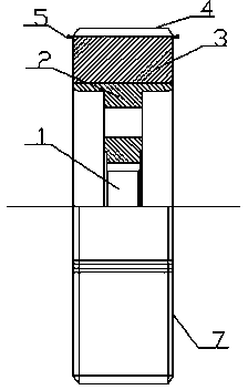
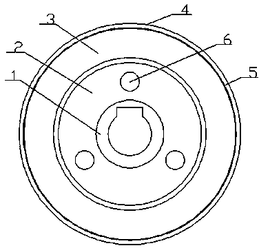
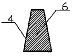
[0014] like figure 1 , figure 2 As shown, a textile machine gear includes a gear sleeve 1 and a gear hub 2. The gear sleeve 1 and the gear hub 2 are integrally processed, and the gear hub 1 is provided with a gear ring 3. The gear ring 3 is provided with straight teeth 4, and the gear ring 3 is provided with an oil guiding groove 5, such as image 3 As shown, the surface of the straight tooth 4 is provided with a wear-resistant layer 6, the thickness of the wear-resistant layer 6 is 0.02 mm to 0.05 mm, and the gear hub 2 is provided with a hole 7, through which the gear ring There is an oil guide groove on the top, which can evenly distribute the lubricating oil to each spur tooth, which improves the lubrication effect and reduces the local da...


PUM


Abstract

The invention discloses a gear of a textile machine and relates to the field of textile mechanical equipment. The gear of the textile machine comprises a gear shaft sleeve and a gear shaft hub, wherein the gear shaft sleeve and the gear shaft hub are machined integrally, a gear ring is arranged on the gear shaft hub, straight teeth are arranged on the gear ring, an oil guiding groove is formed in the gear ring, a wearing layer is arranged on the surfaces of the straight teeth, and the thickness of the wearing layer is 0.02-0.05mm. According to the gear of the textile machine, due to the fact that holes are formed in the gear shaft hub and the oil guiding groove is formed in the gear ring, lubricating oil can be evenly distributed to each straight tooth, the lubricating effect is improved, and local damage to the straight teeth is reduced; due to the fact that the wearing layer is arranged on the surfaces of the straight teeth, abrasion-resisting performance of the straight teeth can be greatly improved, and the service life is prolonged; due to the fact that the holes are formed in the gear shaft hub, weight of the gear can be reduced, and materials are saved. The gear of the textile machine is suitable for being popularized and used.

Description

technical field [0001] The invention relates to the field of textile machinery equipment, in particular to a textile machine gear. Background technique [0002] Entering the 21st century, the world is constantly developing. China's textile industry has also made great progress during this period, including the field of textile machinery and equipment. With the development of science and technology, people have put forward higher requirements for product quality. requirements, the application number is CN201220155826.1 discloses a textile machine gear, including the gear sleeve and the gear hub, the gear sleeve and the gear hub are integrally processed, and the two sides are flush, the gear hub peripheral only A circle of gear ring, the gear ring and the gear hub are integrally processed, the gear ring is composed of several helical teeth arranged on the peripheral surface of the gear hub, and the inner wall of the gear sleeve is provided with key grooves, the gear can be eff...

Claims


Application Information

Patent Timeline
Patent Type & Authority Applications(China)
IPC IPC(8): F16H55/17F16N1/00
CPCF16H55/17F16H57/0431
Inventor 王振芳
Owner CHANGSHU FANGYUAN TEXTILE EQUIP FACTORY
Why Eureka
Try Eureka