
Biomass wood powder conveying system

A conveying system and biomass technology, applied in the field of material conveying, can solve problems such as difficult to achieve precise control, environmental pollution, reduce the conveying speed of wood powder in the pipeline, and achieve precise control of supply, reduce environmental pollution, and facilitate production planning Effect

Inactive Publication Date: 2014-01-22
GUANGZHOU DEVOTION THERMAL TECH
View PDF6 Cites 6 Cited by
  • Summary
  • Abstract
  • Description
  • Claims
  • Application Information

AI Technical Summary

Problems solved by technology

The disadvantages of this transportation method are: 1. Since there is no silo in front of the boiler as a storage device for wood powder, it needs manual uninterrupted real-time feeding operation, which greatly increases the labor cost; 2. The amount of biomass wood powder entering the furnace is It is determined by the output power of the screw conveyor, and it is difficult to achieve precise control; 3. When targeting a small-load boiler, the air volume of the ventilation fan is lowered, which reduces the conveying speed of wood powder in the pipeline, resulting in wood powder sedimentation in the pipeline and blockage 4. Because wood powder will produce dust, if there is no dust removal equipment, it will pollute the environment

Method used


Image

  • Biomass wood powder conveying system
  • Biomass wood powder conveying system

Examples


Embodiment Construction

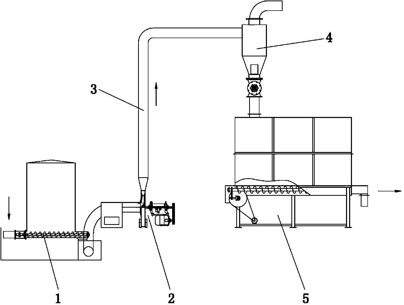
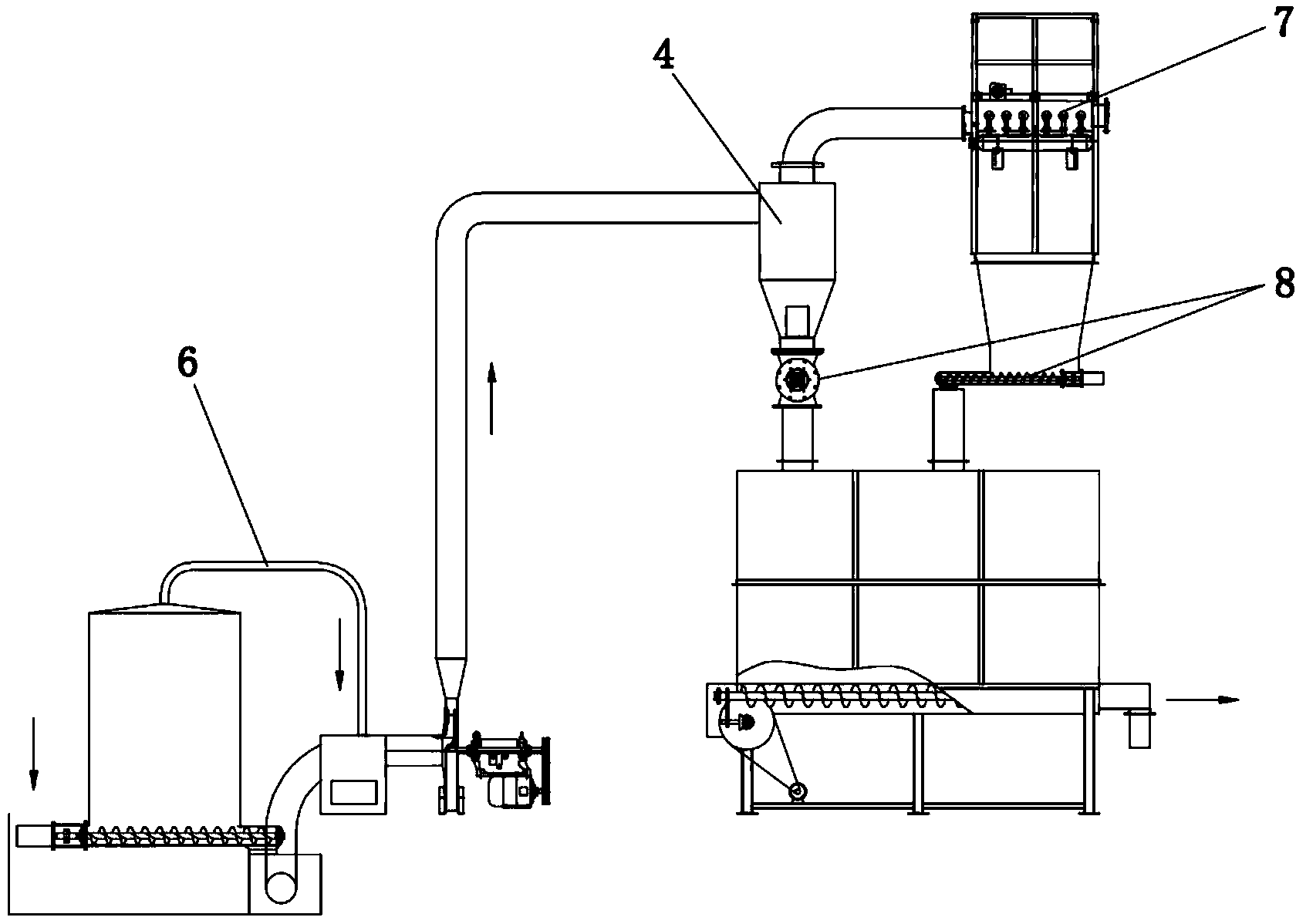
[0013] like figure 1 As shown, the biomass wood flour conveying system is composed of a screw conveyor 1, an induced draft fan 2, a cyclone separator 4 and a feed bin 5 in front of the furnace.

[0014] A screw conveyor 1 is arranged at the bottom of the feeding port of the production workshop, and the screw conveyor can adopt a double-helix structure. The outlet of the screw conveyor 1 is provided with an induced fan 2 , and the induced fan 2 and the cyclone separator 4 are connected through a conveying pipeline 3 . The blanking opening of the cyclone separator 4 is connected to the front feed bin 5 through a pipeline.

[0015] The screw conveyor 1, the induced draft fan 2 and the feed bin 5 are arranged on the first floor of the production workshop, and the cyclone separator 4 is arranged on the second floor of the production workshop.

[0016] The production process of the biomass wood powder conveying system is: the biomass wood powder is put in from the feeding port on ...


PUM


Abstract

The invention discloses a biomass wood powder conveying system. The biomass wood powder conveying system comprises a spiral conveyer and an induced draft fan, wherein biomass wood powder is conveyed into the induced draft fan through the spiral conveyer, an outlet of the induced draft fan is connected with a cyclone separator, a discharge outlet of the cyclone separator is connected with a stokehole bin, the biomass wood powder is conveyed into the cyclone separator under the action of the induced draft fan, air is pumped and separated from the biomass wood powder by the cyclone separator, and the biomass wood powder without air falls into the stokehole bin. According to the biomass wood powder conveying system, a storage function is achieved, the storage volume of fuel can be increased continuously, real-time manual feeding is not needed, and labor cost is saved; due to the fact that the fuel conveyed by the induced draft fan is not directly provided for a terminal equipment furnace, the air volume of the induced draft fan is not influenced by the load condition of the terminal equipment, a constant wind speed is maintained, conveying can be carried out smoothly, and blocking is avoided; due to the fact that clean air is separated from the biomass wood powder by the cyclone separator before the fuel enters the stokehole bin, pollution to the environment is reduced.

Description

technical field [0001] The invention belongs to the field of material conveying, and in particular relates to a conveying system for conveying biomass wood powder to boilers. Background technique [0002] The conveying process of biomass wood powder in the prior art is: first, the screw conveyor at the feeding port sends the biomass wood powder to the inlet of the induced draft fan, and under the negative pressure adsorption of the induced draft fan, it is directly sent to the boiler through the pipeline. combustion. The disadvantages of this transportation method are: 1. Since there is no silo in front of the boiler as a storage device for wood powder, it needs manual uninterrupted real-time feeding operation, which greatly increases the labor cost; 2. The amount of biomass wood powder entering the furnace is It is determined by the output power of the screw conveyor, and it is difficult to achieve precise control; 3. When targeting a small-load boiler, the air volume of t...

Claims


Application Information

Patent Timeline
Patent Type & Authority Applications(China)
IPC IPC(8): F23K3/02B65G53/60B65G53/66
Inventor 常厚春马革张湘波
Owner GUANGZHOU DEVOTION THERMAL TECH
Learn More