
Air conditioner and air guiding device thereof

A technology of air guide device and air guide vane, which is applied in the direction of airflow control components, etc., can solve the problems that the room temperature cannot be adjusted quickly, inconvenient cleaning of air guide vanes and air outlets, and insufficient space, etc., to achieve simple disassembly Ease of operation, small space, and space-saving effect

Active Publication Date: 2014-01-22
TCL AIR CONDITIONER ZHONGSHAN CO LTD
View PDF8 Cites 60 Cited by
  • Summary
  • Abstract
  • Description
  • Claims
  • Application Information

AI Technical Summary

Problems solved by technology

The air guide structure of the existing split wall-mounted air conditioner indoor unit usually fixes the longitudinal air guide vane for left and right swinging wind on the base, the air outlet frame or the air outlet volute tongue, and the longitudinal air guide vane and the horizontal air guide plate (for up and down wind) is a separate setting, which has great restrictions on the air outlet of the indoor unit of the split wall-mounted air conditioner, especially for ultra-thin wall-mounted air conditioners with high requirements for thickness and size , often there is not enough space for arrangement, and the traditional longitudinal vane used for left and right swinging wind is difficult to disassemble, and it is inconvenient to clean the vane and air outlet
In addition, the indoor unit of the ultra-thin split wall-mounted air conditioner is often designed to be relatively thin because of the thickness of the whole unit. In order to compress the space, the width of the air outlet is designed to be relatively narrow. Affect the air supply effect, so that the room temperature cannot be adjusted quickly (heating or cooling)

Method used


Image

  • Air conditioner and air guiding device thereof
  • Air conditioner and air guiding device thereof
  • Air conditioner and air guiding device thereof

Examples


Embodiment Construction

[0034] It should be understood that the specific embodiments described here are only used to explain the present invention, and are not intended to limit the present invention.

[0035] Such as Figure 1 to Figure 12 Shown is a preferred embodiment of the air conditioner of the present invention.

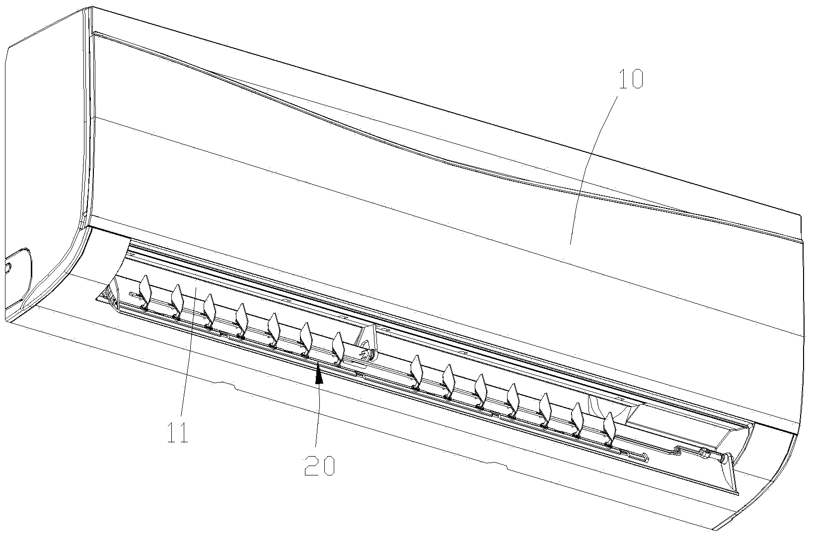
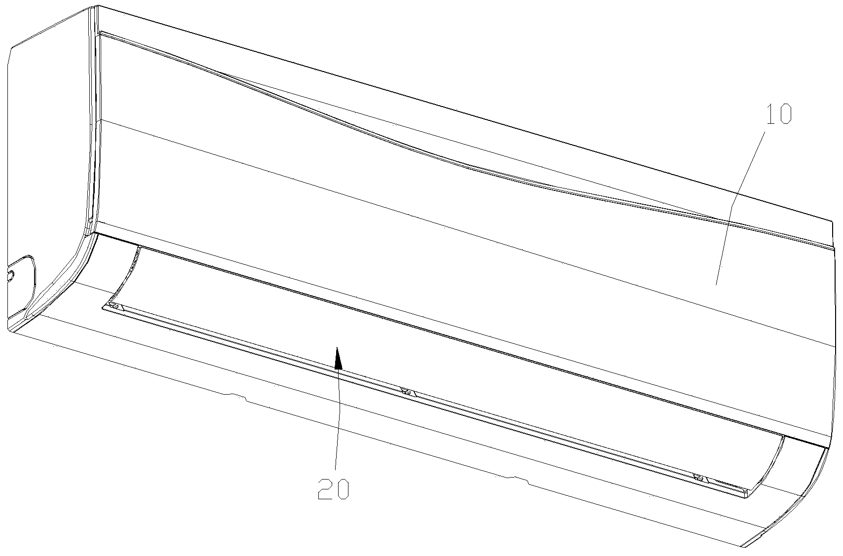
[0036] refer to figure 1 with figure 2, the air conditioner includes a casing 10, the casing 10 is provided with an air outlet 11, and the air outlet 11 is provided with an air guiding device 20.

[0037] In this embodiment, the air conditioner is a split wall-mounted air conditioner indoor unit, and its air outlet 11 is arranged on the front side of the bottom of the casing 10 .

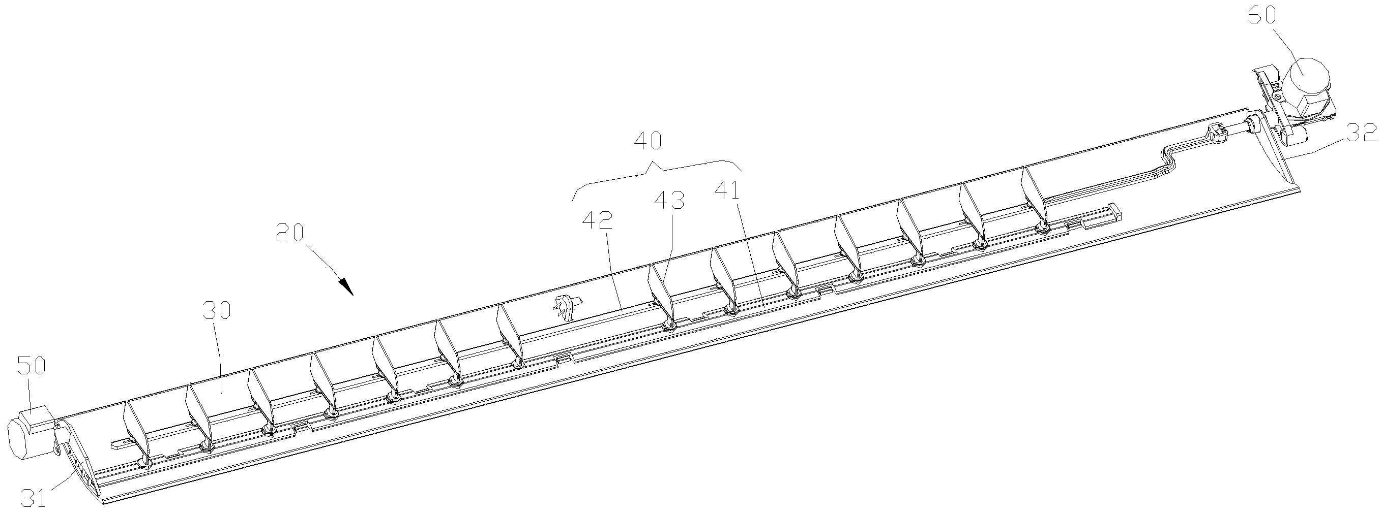
[0038] refer to image 3 , the wind guide device 20 includes a wind guide plate 30, a wind guide vane assembly 40, a first drive mechanism 50 and a second drive mechanism 60, the wind guide vane assembly 40 is installed on the wind guide plate 30, the The first drive mechanism 50 is arranged at one ...


PUM


Abstract

The invention provides an air guiding device. The air guiding device comprises an air guiding plate, an air guiding blade assembly, a first drive mechanism and a second drive mechanism, wherein the air guiding blade assembly is installed on the air guiding plate, the first drive mechanism is arranged at one end of the air guiding plate and is connected with the air guiding plate to drive the air guiding plate to swing up and down to sweep wind, and the second drive mechanism is arranged at the other end of the air guiding plate and is connected with the air guiding blade assembly to drive the air guiding blade assembly to swing left and right to sweep wind. The air guiding blade assembly comprises a blade fixing rod, a blade connecting rod and a plurality of air guiding blades, each air guiding blade comprises a sheet-shaped body, a first installing part and a second installing part, wherein the first installing part and the second installing part are installed at the bottom of the body, and each air guiding blade is detachably connected with the blade fixing rod and the blade connecting rod through the first installing part and the second installing part. The air guiding device has the advantages of being small in occupied space and convenient to dismount and wash. The invention further provides an air conditioner with the air guiding device.

Description

technical field [0001] The invention relates to the technical field of air conditioners, in particular to an air conditioner and an air guide device thereof. Background technique [0002] At the air outlet of the air conditioner, for example, the air outlet of the indoor unit of the split wall-mounted air conditioner is usually provided with an air guide structure to expand the air supply angle. The air guide structure of the existing split wall-mounted air conditioner indoor unit usually fixes the longitudinal air guide vane for left and right swinging wind on the base, the air outlet frame or the air outlet volute tongue, and the longitudinal air guide vane and the horizontal air guide plate (for up and down wind) is a separate setting, which has great restrictions on the air outlet of the indoor unit of the split wall-mounted air conditioner, especially for ultra-thin wall-mounted air conditioners with high requirements on thickness and size , often there is not enough s...

Claims


Application Information

Patent Timeline
IPC IPC(8): F24F13/15
Inventor 林进
Owner TCL AIR CONDITIONER ZHONGSHAN CO LTD
Features
  • Generate Ideas
  • Intellectual Property
  • Life Sciences
  • Materials
  • Tech Scout
  • Unparalleled Data Quality
  • Higher Quality Content
  • 60% Fewer Hallucinations
Learn More