A mine fiber grating roof detachment monitoring device and monitoring method

A fiber grating and roof separation technology, which is applied in the direction of using optical devices, measuring devices, mining devices, etc., can solve the problem that the automatic continuous monitoring and data transmission of roof separation cannot be realized, the safety and reliability of roadways and mining projects. It can solve problems such as early warning of abscission data, and achieve the effect of good monitoring effect, strong anti-electromagnetic interference ability, and avoidance of roof collapse accidents.

Active Publication Date: 2015-10-14
CHINA UNIV OF MINING & TECH
View PDF7 Cites 0 Cited by
  • Summary
  • Abstract
  • Description
  • Claims
  • Application Information

AI Technical Summary

Problems solved by technology

[0003] At present, the roof separation monitoring devices commonly used in my country's coal mines are mostly mechanical roadway roof separation indicators and roadway roof separation indicators that use electrical components to alarm by sound and light. Although these methods play a positive role in preventing roof caving However, the above-mentioned monitoring methods still have the following disadvantages: they all use manual timing to observe and measure the roof abscission state, which is inconvenient to read underground, the readings have large artificial errors, and the accuracy is not high, and cannot realize automatic continuous monitoring and data transmission of the roof abscission layer. At the same time, the data of the roof separation layer cannot be well warned, which has a great impact on the safety and reliability of the roadway and mining engineering.

Method used


Image

  • A mine fiber grating roof detachment monitoring device and monitoring method
  • A mine fiber grating roof detachment monitoring device and monitoring method
  • A mine fiber grating roof detachment monitoring device and monitoring method

Examples


Embodiment Construction

[0034] Embodiments of the present invention will be further described below in conjunction with the accompanying drawings:

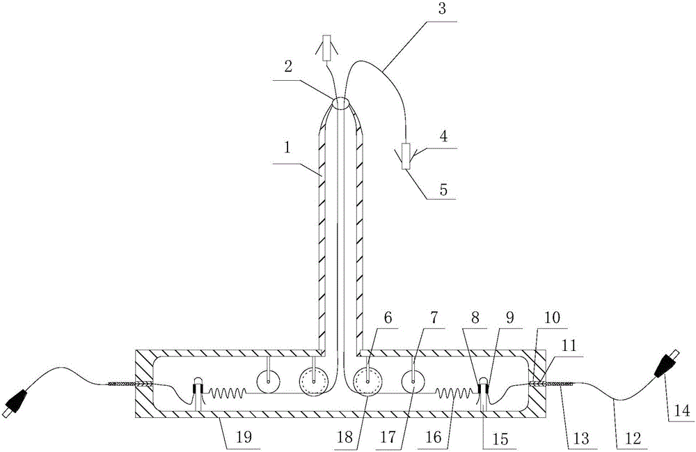
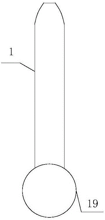
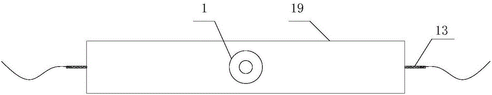
[0035] As shown in the figure, the fiber grating roof detachment monitoring device for mining of the present invention includes a vertical measuring cylinder 1 arranged in the drilling hole of the roof, the diameter of the vertical measuring cylinder 1 is 30-35mm, and the length is 250-350mm. The casing 19 is connected to the lower end of the vertical measuring cylinder 1, and the fixed pulley fixing frame 6 and the steel pulley fixing frame 7 are symmetrically arranged on the upper part of the packaging casing 19, and the equal strength cantilever beam 15 is symmetrically arranged on the lower part, and the left and right sides of the packaging casing 19 Optical fiber export holes 10 are opened symmetrically on the side, a fixed pulley 18 is provided on the pulley fixed frame 6, a steel belt pulley 17 is provided on the steel belt wheel fixed frame 7, an...


PUM


Abstract

An apparatus for monitoring a mining fiber grating roof separation layer comprises a perpendicular measurement barrel (1) disposed in roof drill hole and a packaging housing (19) connected under the perpendicular measurement barrel (1). Fixed-pulley fixed-frames (6) and steel tape pulley fixed-frames (7) are symmetrically disposed on the upper portion of the packaging housing (19), and constant-strength cantilever beams (15) are symmetrically disposed on the lower portion. Tension springs (16) are disposed on opposite ends of the constant-strength cantilever beams (15). The other ends of the two tension springs (16) are connected to a steel wire rope (3). The steel wire rope (3) passes through steel tape pulleys (17) and fixed pulleys (18), and penetrates out from a steel wire rope led-out hole (2) on the top of the perpendicular measurement barrel (1). The end head of the steel wire rope (3) is connected to an anchorage head (5). Fiber gratings A (8) and fiber grating B (9) are symmetrically disposed at left sides and right sides of the constant-strength cantilever beams (15). The fiber gratings A (8) and the fiber gratings B (9) penetrate out from a fiber led-out hole (10) through a same fiber (12) and are connected to a fiber connector (14). Also disclosed is a method for monitoring a mining fiber grating roof separation layer by using the apparatus for monitoring a mining fiber grating roof separation layer.

Description

technical field [0001] The invention relates to a monitoring device and a monitoring method, in particular to a mining optical fiber grating roof separation monitoring device and monitoring method suitable for the measurement and early warning of roof collapse in coal mine roadways and mining working faces. Background technique [0002] In recent years, with the continuous improvement of my country's coal mining technology, my country's coal mining industry has achieved better and faster development. However, with the continuous deepening of coal mining depth, the mine pressure of coal mines has become more obvious, and the disasters caused have become more and more serious. Roof detachment is one of the main forms of deformation and damage of roadway surrounding rock. For bolted roadways, roof detachment is the biggest safety hazard; the detachment data of the roof of the roadway needs to be monitored at any time in order to understand the anchorage. The rationality of the ...

Claims


Application Information

Patent Timeline
Patent Type & Authority Patents(China)
IPC IPC(8): G01B11/02
CPCE21D21/0093E21C39/00E21F17/18
Inventor 方新秋梁敏富吴刚刘晓宁刘宗柱樊海亮刘兴国
Owner CHINA UNIV OF MINING & TECH
Why Eureka
Try Eureka