
Multi-objective visual guide driving device of automated guided vehicle and collaborative calibration method of multi-objective visual guide driving device

A technology of automatic guided vehicles and driving devices, which is applied in two-dimensional position/channel control, image data processing, instruments and other directions to achieve the effect of eliminating distortion and distortion

Active Publication Date: 2014-01-22
NANJING UNIV OF AERONAUTICS & ASTRONAUTICS
View PDF2 Cites 24 Cited by
  • Summary
  • Abstract
  • Description
  • Claims
  • Application Information

AI Technical Summary

Problems solved by technology

Although the traditional calibration method can obtain the external parameters of the camera, the parameters are only the pose relationship between the target coordinate system and the camera coordinate system
In the visual guidance application of automatic guided vehicles, it is also necessary to obtain the pose relationship between the camera coordinate system and the vehicle motion control coordinate system. It is difficult to measure the target relative to the The vehicle motion control coordinate system is precisely placed

Method used


Image

  • Multi-objective visual guide driving device of automated guided vehicle and collaborative calibration method of multi-objective visual guide driving device
  • Multi-objective visual guide driving device of automated guided vehicle and collaborative calibration method of multi-objective visual guide driving device
  • Multi-objective visual guide driving device of automated guided vehicle and collaborative calibration method of multi-objective visual guide driving device

Examples


Embodiment Construction

[0040] The present invention will be further described below in conjunction with the accompanying drawings.

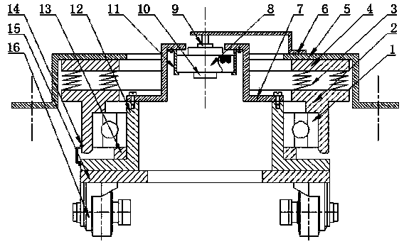
[0041] The structure of the visual guidance driving device provided by the present invention is as follows: figure 1 shown. The visual guidance driving device is fixedly connected to the body of the automatic guided vehicle through a fixed plate (5). Each device includes a shock absorbing unit, a driving unit and a visual unit. Multi-eye vision system for leading vehicles.

[0042] Four shock absorbing springs (3) are arranged coaxially and symmetrically between the top layer (4) of the shock absorbing unit and the bottom layer (2) of the shock absorbing unit, and the top layer (4) of the shock absorbing unit is welded coaxially to the fixing plate (5). The drive unit includes a hollow short shaft (12), a chassis (15) and an electric drive wheel (16), and the hollow short shaft (12) is coaxially assembled with the bottom layer of the damping unit (2) through a deep g...


PUM


Abstract

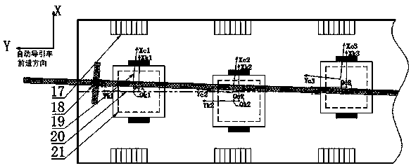
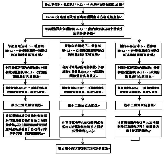
The invention provides a multi-objective visual guide driving device of an automated guided vehicle and a collaborative calibration method of the multi-objective visual guide driving device. A vehicle body of the automated guided vehicle is fixedly connected with a plurality of guide driving devices, each guide driving device comprises a shock absorption unit, a driving unit and a visual unit, each visual unit is provided with a camera, and the cameras arranged on a plurality of guide driving devices form a multi-objective visual system of the automated guided vehicle. The structural characteristic that each single guide device can rotate around a hollow short shaft is utilized, the position posture relationship between a scene coordinate system and each guide driving device movement control coordinate system and the position relationship between the scene coordinate system and the vehicle body movement are jointly established by static calibration and dynamic calibration methods, and the mutation distortion, the proportion distortion and the inclination distortion of visual imaging and the installation position error of a plurality of cameras are effectively eliminated. The method can be used for the multi-objective visual precise measurement of the automated guided vehicle on the basis of plane vector diagrams, the use of precise measuring instruments is not needed, and the characteristics of good operability and high flexibility are realized.

Description

technical field [0001] The invention relates to the field of computer vision detection, in particular to a multi-eye vision guidance drive device for an automatic guided vehicle and a collaborative calibration method thereof. Background technique [0002] Automated guided vehicle (AGV) is a wheeled mobile robot widely used in factory automation production lines, warehouse logistics, material transfer in airports and ports. Its guidance method is one of the core technologies for automatic guided vehicles to realize automatic transportation, which not only determines the flexibility of the automatic transportation system composed of it, but also affects the reliability of system operation and configuration costs. The multi-eye vision guidance method is to form the multi-eye vision system of the automatic guided vehicle through the cameras installed on each guidance drive device, and use the system to collect the images of the guidance path laid on the ground, and use the compu...

Claims


Application Information

Patent Timeline
IPC IPC(8): G05D1/02G06T7/00
Inventor 武星楼佩煌钱晓明石陈陈王龙军朱琳军刘旭沈伟良
Owner NANJING UNIV OF AERONAUTICS & ASTRONAUTICS
Learn More