
Band-pass cavity body filter with suppression degree adjustable function

A cavity filter and filter technology, which is applied in the field of filters, can solve the problems of lower production efficiency, non-adjustable rejection of band-pass cavity filters, and large electrical performance errors.

Inactive Publication Date: 2014-01-22
PIVOTONE COMM TECH
View PDF6 Cites 0 Cited by
  • Summary
  • Abstract
  • Description
  • Claims
  • Application Information

AI Technical Summary

Problems solved by technology

When the low-pass filter with coaxial structure is used in the band-pass cavity filter, the electrical performance error will be large due to high frequency, processing tolerance, matching, etc. If both ends of the band-pass cavity filter are waveguide interfaces , you need a large enough space to match, which will also bring many uncertain factors to the electrical performance of the band-pass cavity filter. Therefore, the method of adding a low-pass filter to the band-pass cavity filter is adopted , will degrade the performance of the bandpass cavity filter
Moreover, the low-pass filter of the above two structural forms is not adjustable to the suppression degree of the band-pass cavity filter, which greatly reduces the production efficiency

Method used


Image

  • Band-pass cavity body filter with suppression degree adjustable function
  • Band-pass cavity body filter with suppression degree adjustable function

Examples


Embodiment Construction

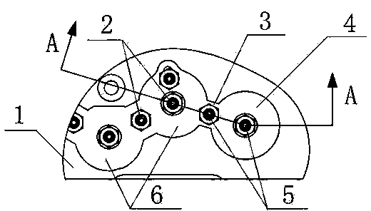
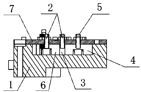
[0010] like figure 1 and figure 2 As shown, the bandpass cavity filter with adjustable rejection function of the present invention includes a filter body 1 . The filter body 1 is in the shape of a flat plate, and at least two blind holes (the specific number depends on the need) for the first resonant cavity 6 are processed on one side, and coupling holes are processed between adjacent first resonant cavities 6. The window 3 makes the two adjacent first resonant cavities 6 communicate with each other. A cover plate 7 is provided on one side of the filter body 1 adjacent to the mouth of the first resonant cavity 6, and the cover plate 7 corresponding to the first resonant cavity 6 and the cover plate 7 corresponding to the coupling window 3 are both Screw holes are processed, and first tuning screws 2 are arranged in the screw holes for frequency adjustment. A second resonant cavity 4 for adjustment of suppression is processed at the first first resonant cavity 6 adjacent t...


PUM


Abstract

The invention relates to a band-pass cavity body filter with a suppression degree adjustable function. The filter comprises a filter body, wherein at least two blind holes as first resonant cavities are formed on one side of the filter body, and a coupling window is arranged between every two adjacent resonant cavities. A cover plate is arranged on one side, adjacent to mouths of the first resonant cavities, of the filter body; screw holes are formed in positions, corresponding to the first resonant cavities and the coupling windows, of the cover plate; and first tuning screws are assembled in the screw holes. The filter is characterized in that second resonant cavities for adjusting a suppression degree are arranged on the filter body where the first resonant cavities are located; coupling windows are arranged between the second resonant cavities and the first resonant cavities; screw holes are formed in positions, opposite to the coupling windows and the second resonant cavities, of the cover plate; and second adjusting screws are assembled in the screw holes. With the adoption of the filter, the processing difficulty can be reduced, and the performances and production efficiency are improved.

Description

technical field [0001] The invention relates to a filter. Specifically, it is a band-pass cavity filter with a function of adjusting rejection. Background technique [0002] It is known in the field of wireless communication equipment manufacturing that a bandpass cavity filter is an important part of communication equipment. With the development of communication technology, the requirements of communication system equipment for band-pass cavity filters are constantly improving, especially the electrical performance indicators of band-pass cavity filters. Communication systems require band-pass cavity filters to There is a certain degree of rejection at three times or even four times the frequency, and often the parasitic passband of the bandpass cavity filter will affect its rejection at the double frequency. In order to solve this problem, the traditional method is to add a low-pass filter in the band-pass cavity filter, and achieve the suppression effect through the low...

Claims


Application Information

Patent Timeline
Patent Type & Authority Applications(China)
IPC IPC(8): H01P1/212
Inventor 项显殷实梁国春宋永民林身平
Owner PIVOTONE COMM TECH
Learn More