Synchronous vector control method for two motor linkage systems

A technology of vector control and linkage system, which is applied in the direction of vector control system, motor generator control, electronic commutation motor control, etc., and can solve problems such as inability to meet work requirements

Inactive Publication Date: 2014-01-22
DAYU ELECTRIC
View PDF4 Cites 0 Cited by
  • Summary
  • Abstract
  • Description
  • Claims
  • Application Information

AI Technical Summary

Problems solved by technology

[0002] In practical applications, the linkage system of two AC motors running at the same time generally adopts two sets of control devices for its control, and the two sets of control devices are synchronized through a certain communication method. This method sometimes cannot meet the actual work needs.

Method used


Image

  • Synchronous vector control method for two motor linkage systems

Examples


Embodiment Construction

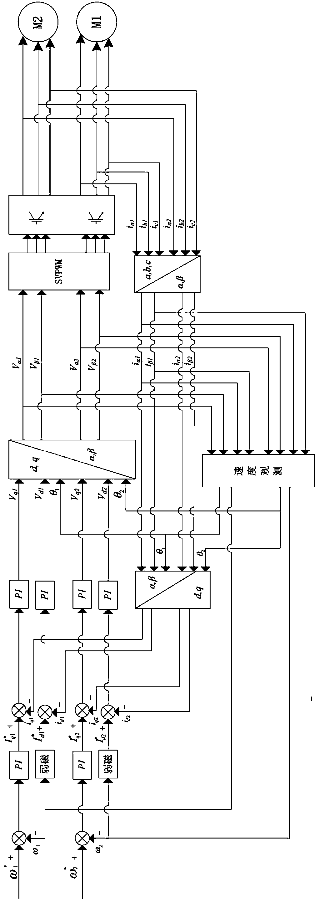
[0017] Such as figure 1 As shown, the control flow chart of a synchronous vector control method for two motor linkage systems described in the embodiment of the present invention, for the synchronous vector control of two AC motor linkage systems, the AC control signal of motor 2 is a three-phase electric current , , , to control motor 1 and motor 2 respectively:

[0018] Three-phase current of motor 1 , , and the three-phase current of motor 2 , , At the same time, the same abc / αβ coordinates are used for synchronous transformation, and the three-phase currents of the two motors are respectively transformed into the same two-phase static αβ coordinate system to obtain the current of motor 1 , and motor 2 current , ;

[0019] The voltage of motor 1 in the two-phase static αβ coordinate system calculated according to the previous cycle , and motor 2 voltage , , to observe the speed and estimate the speed of the two motors , and rotor rotati...


PUM


Abstract

The invention relates to a synchronous vector control method for two motor linkage systems. The method comprises the following steps: synchronously acquiring signals of two motors to convert coordinates; synchronously sampling external signals, and synchronously converting from a three-phase static coordinate system to a two-phase static coordinate system; observing the speed; converting from the two-phase static coordinate system to a two-phase rotating coordinate system; synchronously regulating PI; synchronously converting from the two-phase rotating coordinate system to the two-phase static coordinate system; synchronously implementing the modulation output of SVPWM. The synchronous vector control method has the following benefits: the sampling and the data processing are synchronously implemented for all signals of the two motors; the vector control of movement states of the two motors is implemented only through one algorithm without the coordination of other controllers; the synchronous vector control method can control parameters such as rotating directions, operation speeds and moment output states of the motors.

Description

technical field [0001] The invention relates to the field of motor control, in particular to a synchronous vector control method for two motor linkage systems. Background technique [0002] In practical applications, the linkage system of two AC motors running at the same time generally adopts two sets of control devices respectively, and the two sets of control devices are synchronized through some communication method. This method sometimes cannot meet the actual work requirements. Contents of the invention [0003] The purpose of the present invention is to provide a synchronous vector control method for two motor linkage systems to overcome the above-mentioned shortcomings in the prior art. [0004] The purpose of the present invention is to realize through the following technical solutions: [0005] A synchronous vector control method for two motor linkage systems, comprising the following steps: [0006] 1) Collect the three-phase AC signals of the two motors , ...

Claims


Application Information

Patent Timeline
Patent Type & Authority Applications(China)
IPC IPC(8): H02P21/00
Inventor 毛康宇宁国云王怡华程世国
Owner DAYU ELECTRIC
Why Eureka
Try Eureka