Signal propagation time measuring means

A technology of time measurement and signal propagation, applied in telemetry/remote control selection devices, selection devices, transmission systems, etc., can solve the problems of increased component cost and complicated receiving circuit components, and achieve the effect of simplifying the structure

Active Publication Date: 2014-01-22
KK TOKAI RIKA DENKI SEISAKUSHO
View PDF9 Cites 6 Cited by
  • Summary
  • Abstract
  • Description
  • Claims
  • Application Information

AI Technical Summary

Problems solved by technology

However, this leads to a complication of the receiving cir

Method used


Image

  • Signal propagation time measuring means
  • Signal propagation time measuring means
  • Signal propagation time measuring means

Examples


Embodiment Construction

[0021] Below, according to Figure 1-Figure 8 The signal propagation time measurement device of the first embodiment will be described.

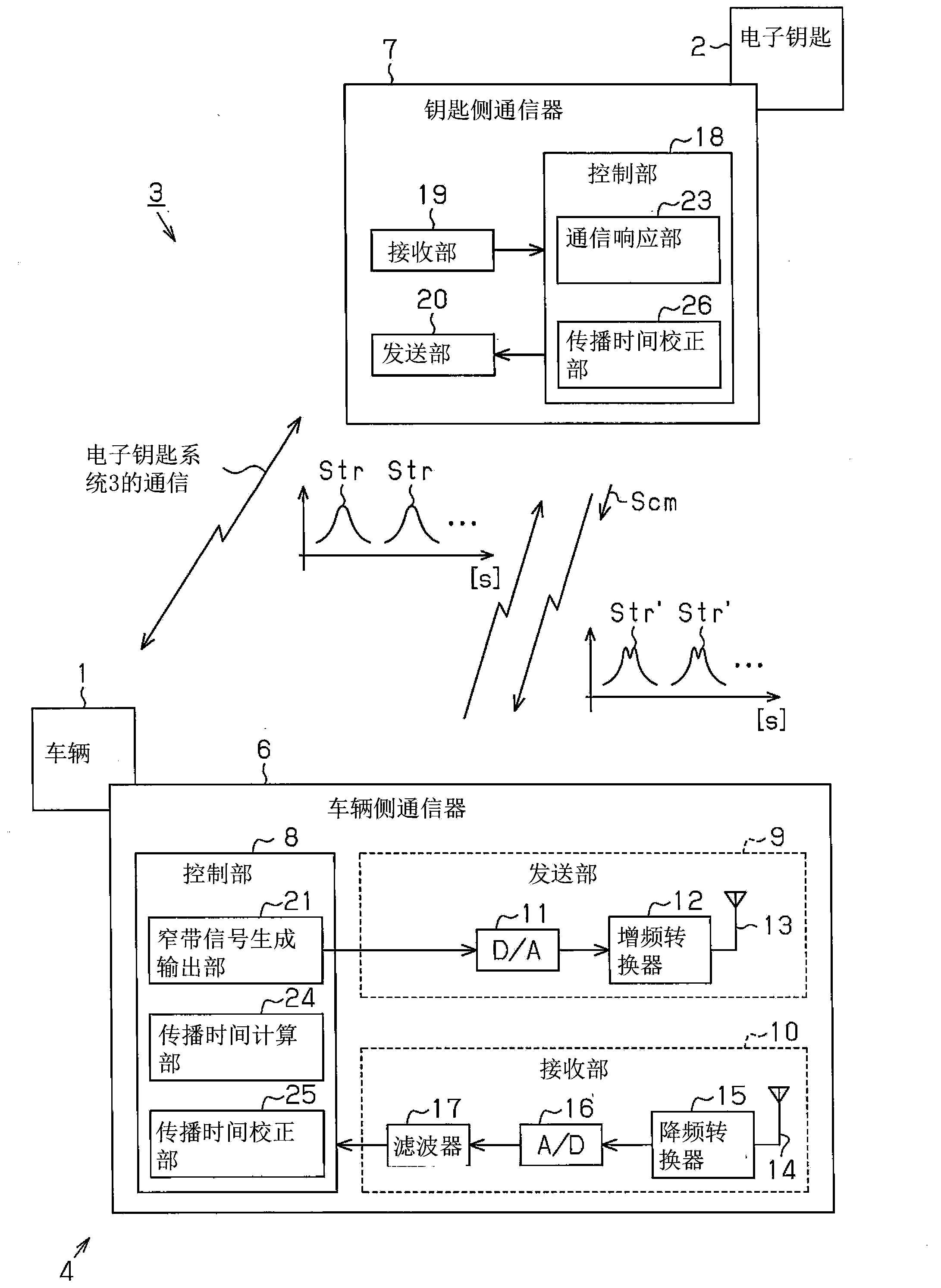
[0022] like figure 1 As shown, in the electronic system 3 , the vehicle 1 performs ID verification of the electronic key 2 through wireless communication with the electronic key 2 . When the ID verification of the electronic key 2 is established, for example, locking / unlocking of the vehicle doors and starting of the engine are permitted. The electronic key system 3 includes, for example, a keyless operation system that performs ID verification based on communication from the vehicle 1 , and a wireless key system that performs ID verification based on communication from the electronic key 2 .

[0023] The electronic key system 3 includes a signal propagation time measuring device 4 that measures the propagation time of a signal sent from the vehicle 1 and returned to the vehicle 1 via the electronic key 2 . For example, the vehicle 1 tra...


PUM


Abstract

The present invention provides a simple configuration of the signal propagation time measurement of the propagation time measuring means. A signal transfer time measurement apparatus (4) measures a transfer time (TX) of a signal transmitted from a base station (1) and returned via a terminal (2) to the base station (1). The signal transfer time measurement apparatus includes a signal processor (21) that divides the signal (Str) into a plurality of frequency bands (22) and transmits the signal in the plurality of frequency bands.

Description

technical field [0001] The present invention relates to a signal propagation time measuring device for measuring the propagation time of a signal communicating between a base station and a terminal. Background technique [0002] The signal propagation time measuring device measures the time from when a base station transmits a signal (radio wave) to a terminal until when the base station receives the signal (radio wave) transmitted from the terminal. Japanese Patent Publication No. 9-170364, Japanese Patent Application Publication No. 2003-13644, Japanese Special Publication No. 2006-512515, and Japanese Special Publication No. 2008-515315 describe an electronic key system equipped with such a signal propagation time measuring device. . The signal propagation time measuring device measures the signal propagation time between the vehicle and the electronic key when ID verification is performed by wireless communication between the vehicle and the electronic key. Thus, even ...

Claims


Application Information

Patent Timeline
IPC IPC(8): H04B17/00H03J9/02H04Q9/00
CPCB60R25/24H04B17/104H04W24/00
Inventor 古贺健一河村大辅
Owner KK TOKAI RIKA DENKI SEISAKUSHO
Why Eureka
Try Eureka