Water pump shaft grinding device and process

A water pump shaft and grinding technology, which is applied in the direction of grinding workpiece supports, grinding/polishing equipment, grinding machines, etc., can solve the problems that the grinding accuracy is difficult to guarantee, it is difficult to use electromagnetic centerless fixtures, and vibration lines are easy to occur, and achieve The effect of reducing grinding cost, widening the range of processing and convenient debugging

Active Publication Date: 2014-01-29
浙江省新昌新轴实业有限公司
View PDF8 Cites 7 Cited by
  • Summary
  • Abstract
  • Description
  • Claims
  • Application Information

AI Technical Summary

Problems solved by technology

However, due to the particularity of the pump shaft structure, it is difficult to use electromagnetic centerless fixtures
The processing and clamping method of the shaft channel of the existing water pump is that the one-way bearing drives the water pump shaft, supports the shaft with double supports, positions the end face, and then presses the shaft with the pressure roller to carry out the grinding process. Because the one-way bearing requires a certain The clamping position, and the clamping of the double support and the pressure wheel also requires a certain space, which leads to certain limitations in the grinding of the pump shaft, such as many steps, and the pump shaft with a small center distance between the double grooves is not easy to use the above method to process
At present, for the grinding of the steps of the water pump shaft, the plunge grinding is mostly used, but for the longer steps, the grinding accuracy is not easy to guarantee, and it is easy to produce defects such as vibration marks

Method used


Image

  • Water pump shaft grinding device and process
  • Water pump shaft grinding device and process
  • Water pump shaft grinding device and process

Examples


Embodiment Construction

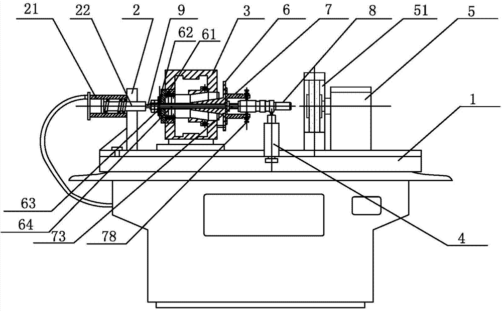
[0026] Such as figure 1 As shown, a water pump shaft grinding device includes a base 1, and an oil cylinder base 2, a head frame 3, a center support 4, and a grinding wheel frame 5 arranged on the upper surface of the base 1 in sequence, and an oil cylinder 21 is installed on one side of the oil cylinder base 2 , the flange 6 is installed on the main shaft 31 of the head frame 3 through the cooperation of the end cover 61 , the thrust bearing 62 and the lock nut 63 in sequence. The film chuck 7 is installed on the main shaft 31 of the head frame 3 through the flange 6, the grinding wheel 51 is installed on the side of the grinding wheel frame 5 close to the film chuck 7, and is used for grinding the water pump shaft 8, and the piston rod 22 of the oil cylinder 21 passes through the push rod 9 is in contact with the center of the film chuck 7, the push rod 9 is slidably installed in the center hole 64 of the flange 6, the above-mentioned piston rod 22, push rod 9, headstock mai...


PUM


Abstract

The invention discloses a water pump shaft grinding device and process and belongs to the field of machinery. The water pump shaft grinding device comprises a base, an oil cylinder base, a head rack, a central bearing and a grinding wheel bracket, wherein the oil cylinder base, the head rack, the central bearing and the grinding wheel bracket are sequentially arranged on the upper surface of the base. A film chuck is mounted on a spindle of the head rack through a flange and provided with a plurality of claws, and the central bearing is perpendicularly mounted between the film chuck and the grinding wheel. By the water pump shaft grinding device and process, a water pump shaft is clamped or unclamped by means of elastic deformation generated by the film chuck, occupation space of the clamping position is few, a bearing surface of a lower bearing is an inclined surface, radial displacement is prevented during grinding, the water pump shaft can be supported by only one central bearing without using a pressing wheel, and accordingly, grinding of steps and grooves of the multi-step water pump shaft with small double-groove center distance is realized.

Description

technical field [0001] The invention relates to a water pump shaft grinding device and a process, belonging to the field of machinery. Background technique [0002] Electromagnetic centerless fixtures are usually used in the grinding of rolling bearing rings, which has become a standardized clamping method in the bearing grinding process. However, due to the particularity of the pump shaft structure, it is difficult to use electromagnetic centerless fixtures. The processing and clamping method of the shaft channel of the existing water pump is that the one-way bearing drives the water pump shaft, supports the shaft with double supports, positions the end face, and then presses the shaft with the pressure roller to carry out the grinding process. Because the one-way bearing requires a certain The clamping position, and the clamping of the double support and the pressure wheel also requires a certain space, which leads to certain limitations in the grinding of the pump shaft,...

Claims


Application Information

Patent Timeline
Patent Type & Authority Applications(China)
IPC IPC(8): B24B19/00B24B41/06
CPCB24B19/00B24B19/06B24B41/06
Inventor 张方安陈伟俞冰奇梁鑫伟
Owner 浙江省新昌新轴实业有限公司
Why Eureka
Try Eureka