Novel jet quenching device with adjustable jet array parameters

A technology of array parameters and quenching device, applied in the direction of quenching device, heat treatment equipment, heat treatment process control, etc., can solve the problem of inability to adjust the quenching parameters of the jet array, and achieve good operability, easy production and installation, and simple device structure. Effect

Inactive Publication Date: 2014-01-29
CHINA AGRI UNIV
View PDF7 Cites 7 Cited by
  • Summary
  • Abstract
  • Description
  • Claims
  • Application Information

AI Technical Summary

Problems solved by technology

However, the nozzles in the existing cooling spray system are fixedly arranged on the spray pipe, and the jet array cannot b

Method used


Image

  • Novel jet quenching device with adjustable jet array parameters
  • Novel jet quenching device with adjustable jet array parameters
  • Novel jet quenching device with adjustable jet array parameters

Examples


Embodiment Construction

[0015] In order to enable those skilled in the art to better understand the solution, the present invention will be further described in detail below in conjunction with the accompanying drawings and specific embodiments.

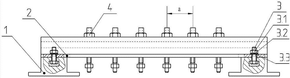
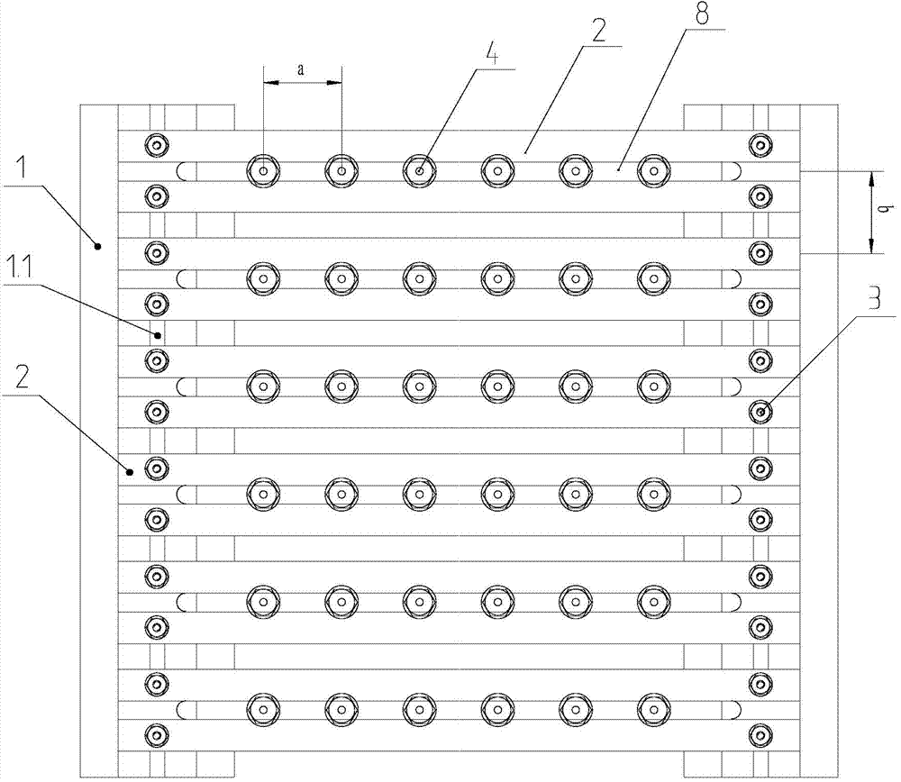
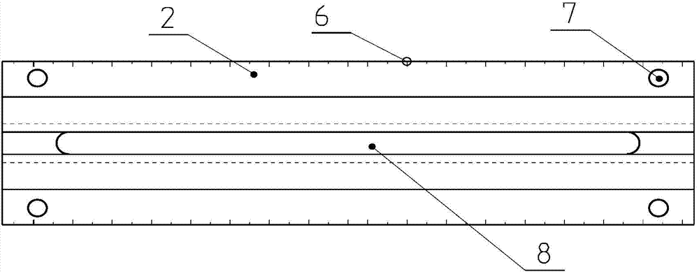
[0016] figure 1 As shown, the present invention is a jet quenching device with adjustable jet array parameters. The device includes a sliding guide rail 1. The sliding guide rail 1 is arranged symmetrically on the left and right and has a T-shaped chute 1.1. T-shaped chute 1.1 is installed inside the T-shaped chute. Screw 3, crossbeam 2 is installed between the two sliding guide rails 1, through-holes 7 are opened at both ends of the crossbeam 2, and the through-holes 7 are mounted on T-shaped screws 3, and T-shaped chute is opened in the crossbeam 2 8. The T-shaped chute 8 is equipped with a slider 9, and the slider 9 is processed with a threaded through hole 10, and the cooling nozzle 4 is connected and installed on the beam 2 through the threaded through...


PUM


Abstract

The invention provides a novel jet quenching device with adjustable jet array parameters, and in particular relates to quenching of an ultra-thin steel plate. The novel jet quenching device consists of sliding guide rails, transverse beams, cooling spray pipes and nozzles. The devices are arranged between conveying roller ways, are vertically paired and are perpendicularly and symmetrically distributed relative to a steel plate to be cooled; the distance between the cooling devices and the steel plate is adjustable. When the steel plate is quenched by the novel jet quenching device, the jet array parameters can be flexibly adjusted according to value simulation and test optimization results, jet quenching is performed according to an optimum array layout, and requirements for hardness and flatness specified by technical conditions are further ensured. By virtue of the device, the quenching quality of the ultra-thin steel plate can be obviously improved. The novel jet quenching device is simple in structure and easy to operate.

Description

technical field [0001] The invention relates to a quenching device and method with continuously adjustable jet array parameters, especially for jet quenching of ultra-thin steel plates, and belongs to the field of heat treatment of metal materials. Background technique [0002] At present, the quenching and cooling method commonly used in the industry is to immerse the whole part in the quenching medium, so that the high-temperature parts are rapidly cooled at a rate greater than the critical cooling rate of the steel, and finally martensite is obtained. However, if the overall quenching is used for ultra-thin steel plates, the contact time between each point of the steel plate and the quenching medium will be inconsistent, that is, the cooling rate will be significantly different. Under the joint action of thermal stress and structural stress, severe deformation or even cracking will occur, and the technical conditions cannot be guaranteed. The specified flatness and hardne...

Claims


Application Information

Patent Timeline
IPC IPC(8): C21D1/667C21D11/00
Inventor 凌刚刘敬徐杨薛党勤张林海沈文道
Owner CHINA AGRI UNIV
Why Eureka
Try Eureka