Manufacturing method and device of transformer molding insulating components
A technology for forming molds and products, applied in textiles and papermaking, etc., can solve the problems of low production efficiency and high price, and achieve the effects of reduced production cost, high electrical strength and high density
- Summary
- Abstract
- Description
- Claims
- Application Information
AI Technical Summary
Problems solved by technology
Method used
Image
Examples
Embodiment 1
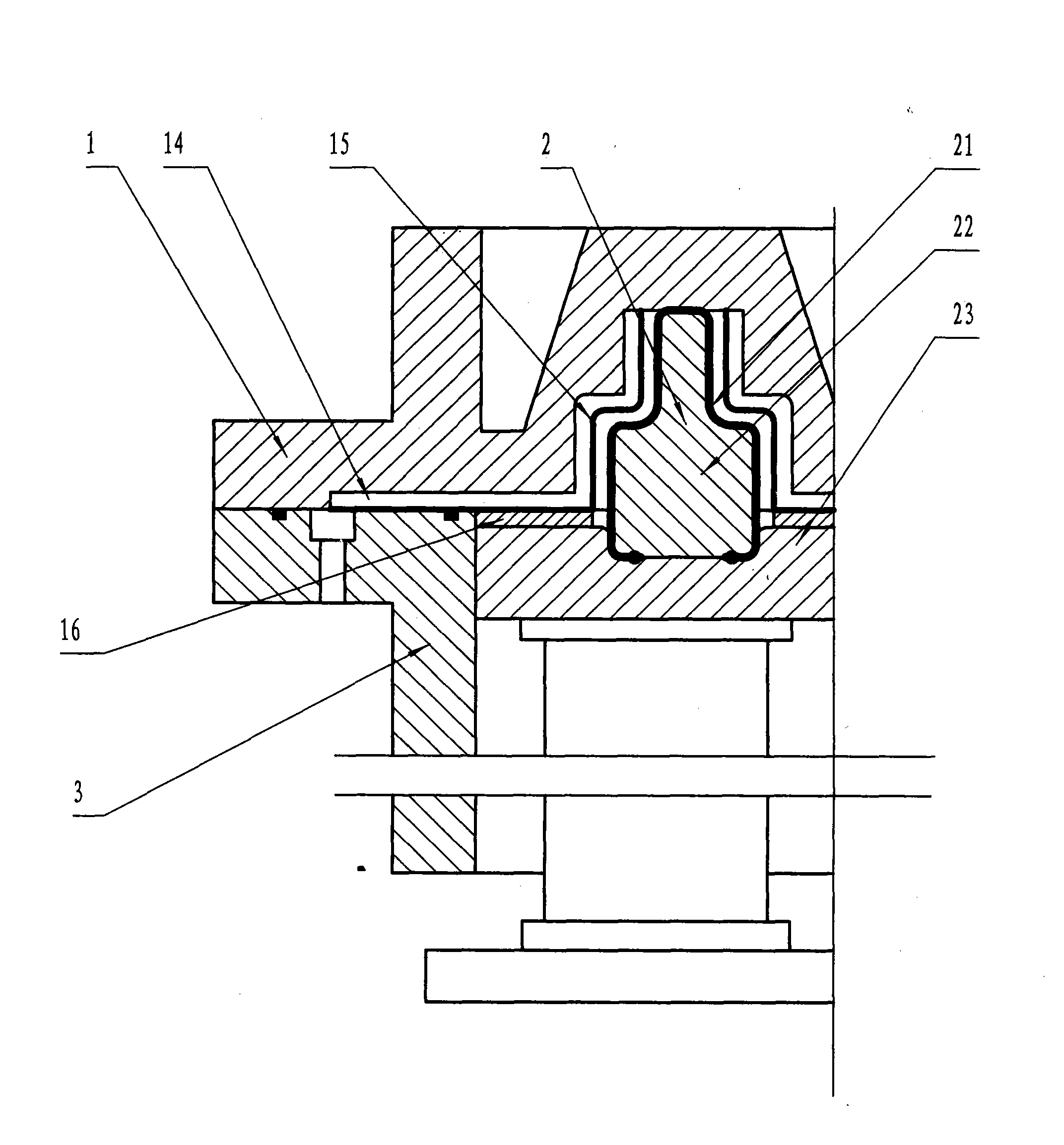
[0024] Embodiment 1: Make the lead angle ring for transformer, the initial pulp concentration is about 0.35%, see figure 1 , the upper mold of the forming mold is a rigid mold 1, and the lower mold is a flexible mold 2; the forming surface of the entire flexible mold 2 is completely covered by a flexible bladder 21 made of elastic material with a thickness of 3 to 5 mm, and the flexible bladder 21 is rigid below. The mold core 22, the two are installed on the flexible mold base 23, and the initial flexible bag 21 is close to the rigid mold core 22; the inner surface of the surrounding frame 3 is cylindrical, and the diameter is based on the enclosed area ≥ product weight / (upper and lower molds are relatively motion maximum stroke × initial pulp concentration) is selected; the drainage groove 14 on the forming surface of rigid mold 1 leads to the drainage channel top on the surrounding frame 3 and the drainage channel (not shown on the figure) on the rigid mold body, and the for...
Embodiment 2
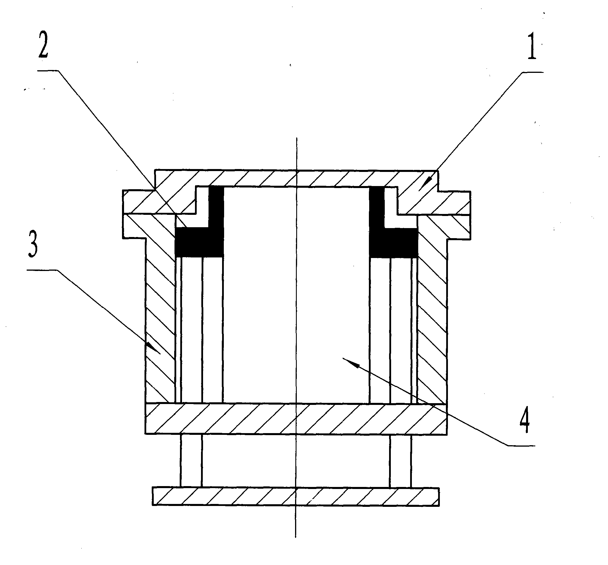
[0026] Embodiment 2: Make the larger transformer body angle ring with inner diameter, see figure 2 , and the difference from Example 1 is that the flexible mold 2 (composed of the flexible bag 21, the mold core 22 and the flexible mold base 23) is a corresponding annular structure, and the dynamic sealing is always set in a diameter smaller than the inner diameter of the insulating angle ring. , a solid or hollow circular cylinder 4, the circular cylinder 4 and the surrounding frame 3 are fixedly connected under the flexible mold, when the rigid mold 1 and the surrounding frame 3 are fastened, the upper end surface of the circular cylinder 4 is just in line with the The rigid mold 1 is in contact.
Embodiment 3
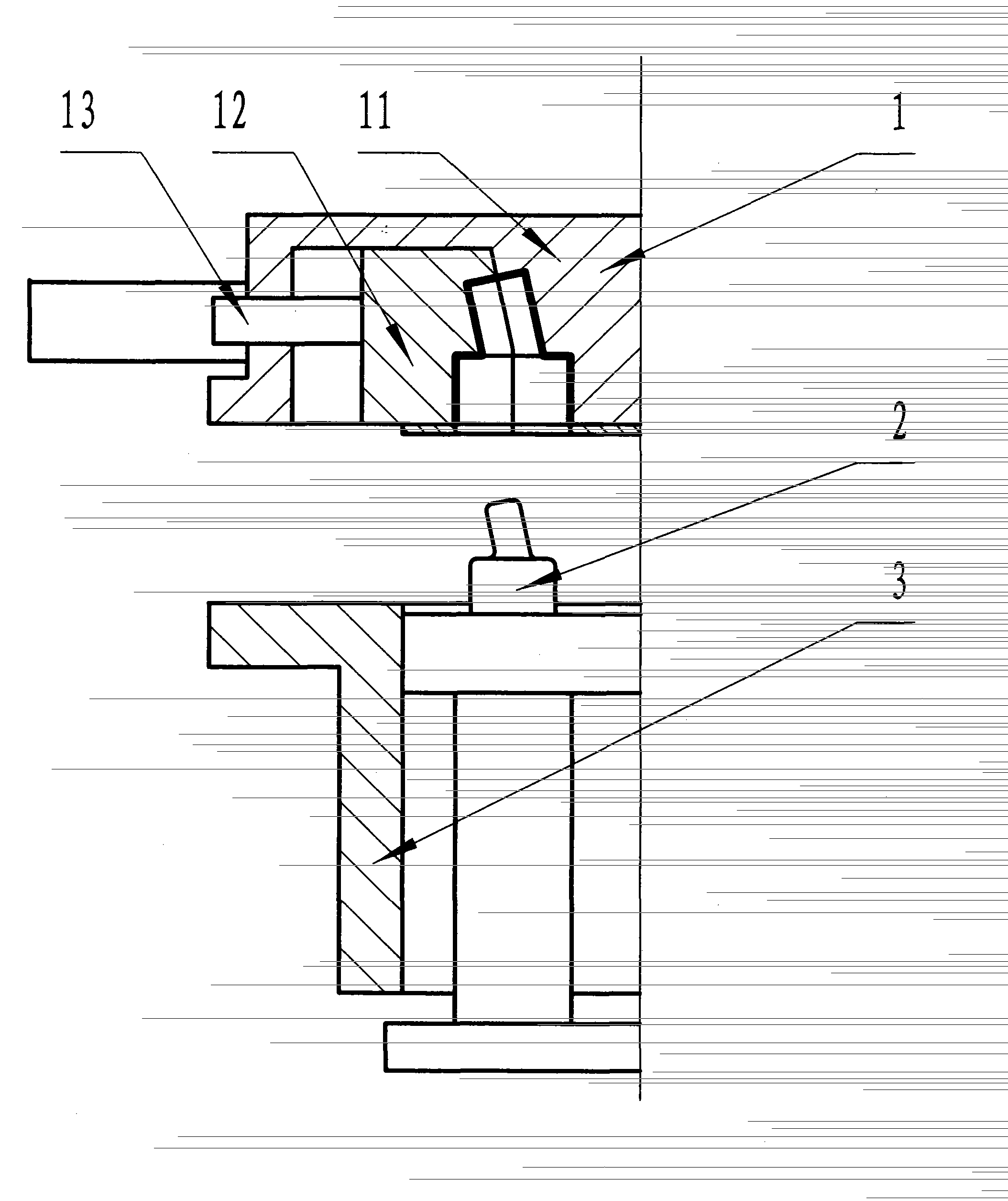
[0027] Embodiment 3: make the lead angle ring with non-orthogonal structure, rigid mold 1 can be made into two lobe molds, see image 3 As shown, the movable mold half 12 is connected with the fixed mold half 11 through the translation device 13; initially, the translation device 13 pushes (pulls) the movable mold half 12 to the fixed mold half 11 and firmly combines with the fixed mold half 11 to form a rigid mold cavity ; After the rigid mold 1 and the flexible mold 2 are relatively moved to squeeze water and the flexible mold 2 is filled with pressure fluid to squeeze water, when the rigid mold 1 is separated from the surrounding frame 3, the wet blank of the product is separated from the rigid mold 1 by introducing compressed air At the same time, use the translation device 13 to quickly separate the movable mold half 12 from the fixed mold half 11, so that the Figure 4 The wet blank of the non-orthogonal shaped part 5 shown can be demolded smoothly. The parting surface ...
PUM
| Property | Measurement | Unit |
|---|---|---|
| Thickness | aaaaa | aaaaa |
| Density | aaaaa | aaaaa |
| Thickness | aaaaa | aaaaa |
Abstract
Description
Claims
Application Information
 - R&D
- Intellectual Property
- Life Sciences
- Materials
- Tech Scout
- Unparalleled Data Quality
- Higher Quality Content
- 60% Fewer Hallucinations
Browse by: Latest US Patents, China's latest patents, Technical Efficacy Thesaurus, Application Domain, Technology Topic, Popular Technical Reports.
© 2025 PatSnap. All rights reserved.Legal|Privacy policy|Modern Slavery Act Transparency Statement|Sitemap|About US| Contact US: help@patsnap.com


