
Foundation element and a complete structure produced therewith

A structure and foundation technology, which is applied in the direction of foundation structure engineering, construction, sheet pile walls, etc., can solve the problems of unstable position of the support part, poor handling performance, heavy weight, etc., achieve cost reduction, improve construction accuracy, eliminate volumetric effect

Inactive Publication Date: 2014-01-29
LASCO JAPAN
View PDF5 Cites 3 Cited by
  • Summary
  • Abstract
  • Description
  • Claims
  • Application Information

AI Technical Summary

Problems solved by technology

[0006] Since such a supporting part is formed in a substantially spherical or substantially ellipsoidal shape, it is bulky and less stable when placed on a flat surface, so it has to be stored in, for example, Handling in a dedicated shovel
Therefore, there is a problem of labor and cost
In addition, the support portion filled with concrete as in the above-mentioned patent document 3 has problems in that it is heavy, has poor handling performance during storage, transportation, etc., and costs a lot.
[0007] In addition, when the support is built on land that is likely to face a cold period, frost may form on the ground during the cold period, thereby causing a so-called permafrost problem in which the support is pushed up, There is a problem that the position of the support portion is unstable
In addition, when the support is built on land that is likely to experience a cold season, the support filled with concrete as in Patent Document 3 may have the following possibility: from the tiny cracks formed on the surface of the concrete. Moisture absorbed by the crevices freezes, causing the concrete to break down due to repeated freezing

Method used


Image

  • Foundation element and a complete structure produced therewith
  • Foundation element and a complete structure produced therewith
  • Foundation element and a complete structure produced therewith

Examples


Embodiment Construction

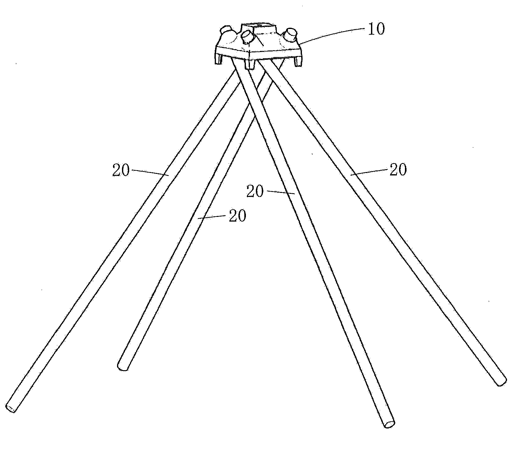
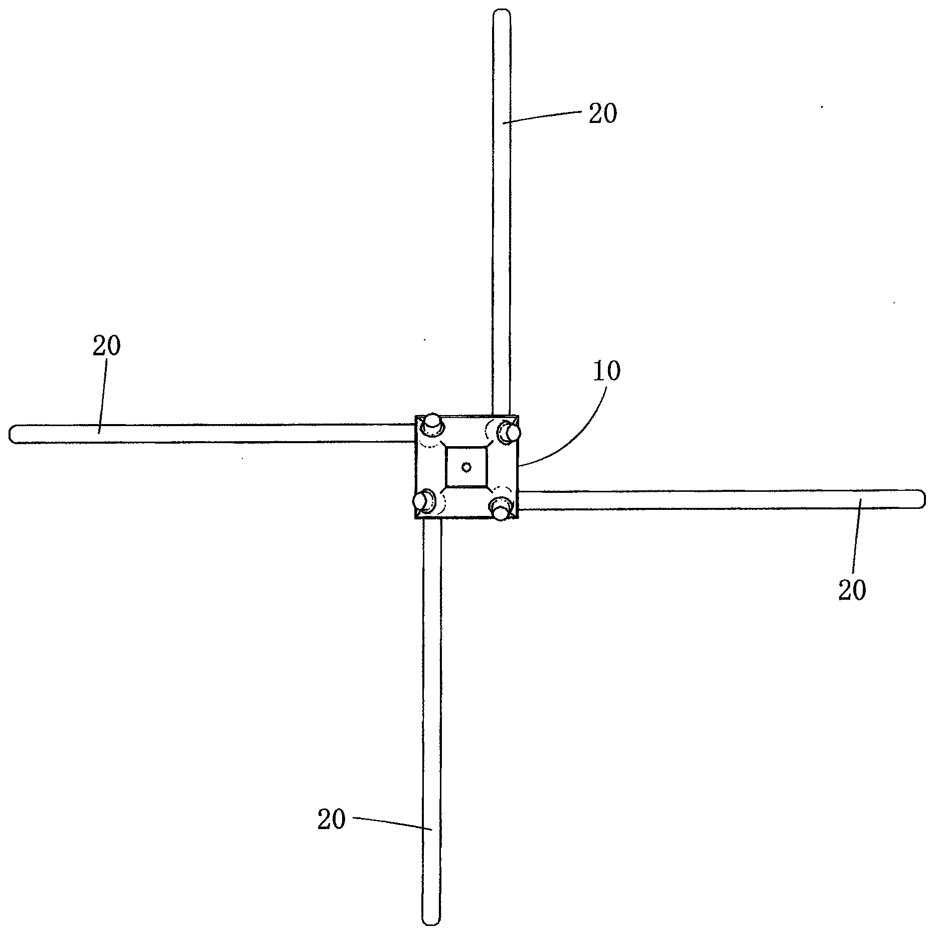
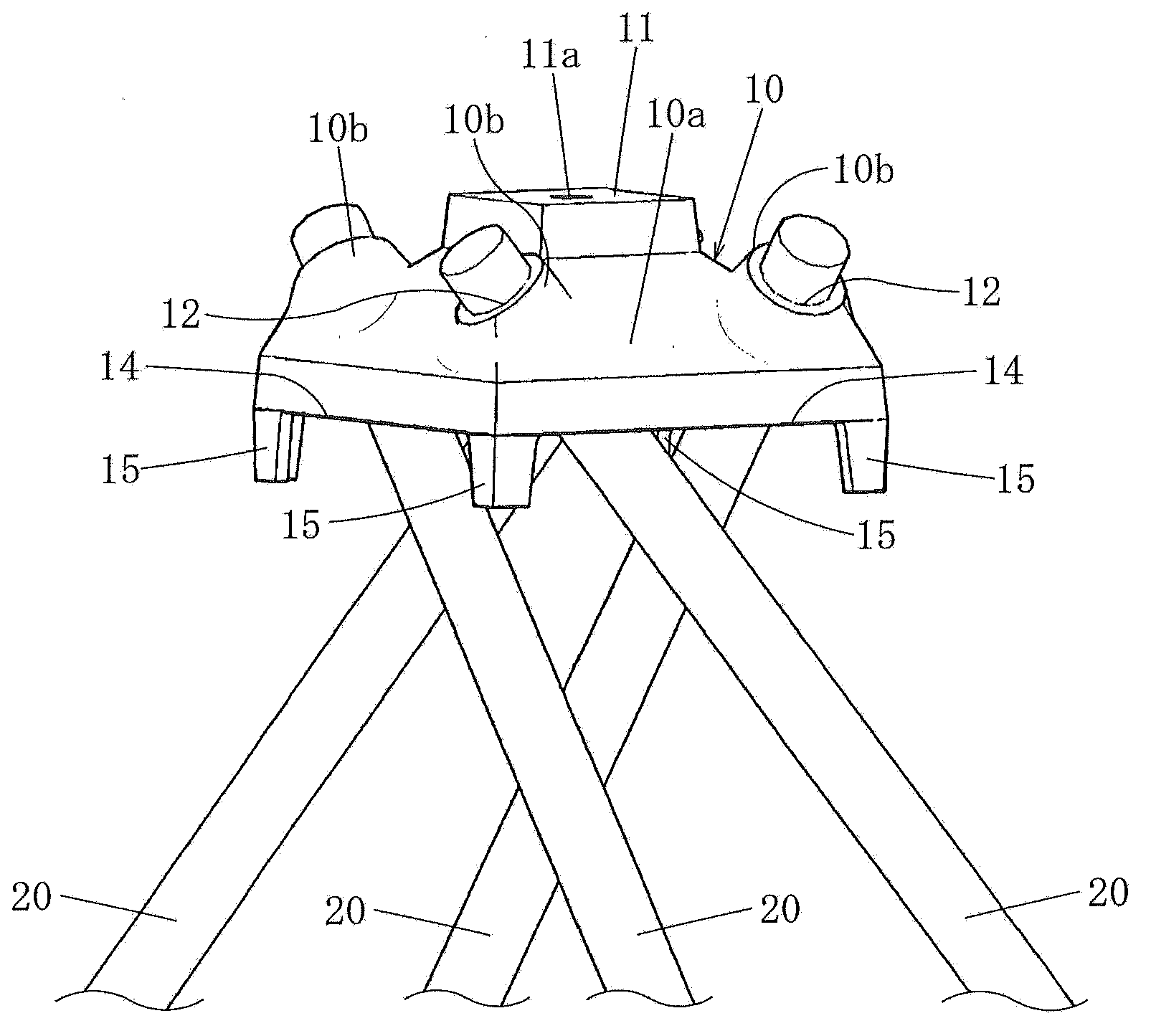
[0027] Figure 1 to Figure 5 The first embodiment of the basic structure of the present invention is shown, Figure 6 One embodiment of the finished structure obtained by assembling the base structure is shown. A foundation assembly is constituted by the foundation structure 10 and a plurality of piles 20 . The base structure 10 has two or more through holes 12 . In this embodiment, four through-holes 12 penetrate through, but the number of the through-holes may be two or more. One end of each of the through holes 12 opens around the central portion 11 on one side of the foundation structure 10 in the height direction, and the other end opens on the other side of the foundation structure 10 in the height direction. . by Figure 5 In other words, the height direction is the up-down direction when the figure is placed in a direction where the symbols can be seen correctly. The height direction includes the vertical direction, but may also form a certain angle with the vert...


PUM


Abstract

The solution, the improving the stability in the mounting, and the possibility of the reduction in weight it grows serious with volume may be referred to the difficult that the in-phase problem happens. Base foundation obtaining and realizes the improvement and cost reduction of handling It is the base foundation in which there is little the concern in which the break down by the moisture freeze occurs. The completed structure water using the base foundation provides. In the base foundation, it does not interfere about the height direction with the angle and it extends as the other direction and one end is opened around the central part of the one-way of the height direction and the through-hole more than opened of the other end is prepared with another side of the height direction. The base foundation puts the respective inserted pile into the through-hole into the underground and it is installed at the land. The base foundation comprises the main body, formed in the inner portion into the bowl form overturned to form the internal space opened to another side of the height direction and the multiple partition members which is formed with the pipe shape and is prepared by the hole of the inner portion in the peripheral part of the main body to form the through-hole through the main body.

Description

technical field [0001] The present invention belongs to the technical field of foundations of structures, and relates to a foundation structure installed on the ground by driving piles fitted and inserted into through holes into the ground, and a completed structure obtained using the foundation structure. Background technique [0002] Patent Document 1 discloses a simple foundation. It is a simple foundation made of metal for supporting the supported body, and it has a supporting part and more than one driving pile. The driving pile is driven into the soil in an inclined state, and the supporting part is used for the a driving pile is inserted, and has a mounting fitting for mounting the supported body on the upper part, the support part is hollow, approximately spherical or approximately ellipsoidal, and is placed so that the lower part of the support part contacts the ground, The driving pile is inserted into a portion inclined into a bowl shape from a portion where the ...

Claims


Application Information

Patent Timeline
IPC IPC(8): E02D5/28E02D27/16
CPCE02D5/223E02D5/54E02D27/14
Inventor 岛谷学
Owner LASCO JAPAN
Learn More