Connection structure of cooling system of refrigerating plant

A cooling system and refrigeration device technology, applied in the direction of refrigerators, refrigeration components, refrigeration and liquefaction, etc., can solve the problems of complex connection, uneven liquid separation, etc., and achieve the effect of flexible application, less transitional pipe fittings, and fewer welding processes

Inactive Publication Date: 2014-01-29
SHENGZHOU XINGAOLUN REFRIGERATION EQUIP
View PDF4 Cites 17 Cited by
  • Summary
  • Abstract
  • Description
  • Claims
  • Application Information

AI Technical Summary

Problems solved by technology

[0006] In order to overcome the above-mentioned defects of complex connection and uneven liquid separation in the prior art, the present invention provides a connection structure for the cooling system of a refrigeration device with convenient processing and simple structure

Method used


Image

  • Connection structure of cooling system of refrigerating plant
  • Connection structure of cooling system of refrigerating plant
  • Connection structure of cooling system of refrigerating plant

Examples


Embodiment 1

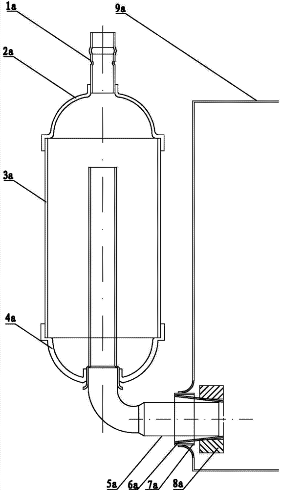
[0024] The connection structure of the cooling system of the refrigeration device in this embodiment, combined with figure 2 , including a liquid receiver, a liquid separator and a compressor. The liquid separator includes an air inlet pipe 1, an upper end cover 2, a middle cylinder body 3, a lower end cover 4 and an air outlet pipe 5. The air outlet pipe 5 of the liquid separator is pressed by an interference fit. Into the cylinder hole 8 of the compressor, the first flange 6 is set between the air outlet pipe 5 and the compressor shell 9, and the first flange 6 is connected with the compressor shell 9 and the air outlet pipe 5 by welding. Among them, interference fit In this embodiment, the outer diameter of the air outlet pipe 5 is 0.005mm up and down the inner diameter of the cylinder bore 8 (that is, if the inner diameter of the cylinder bore 8 is 20mm, the air outlet pipe 5 should be precisely shaped so that the air outlet pipe 5 The outer diameter of the end facing the...

Embodiment 2

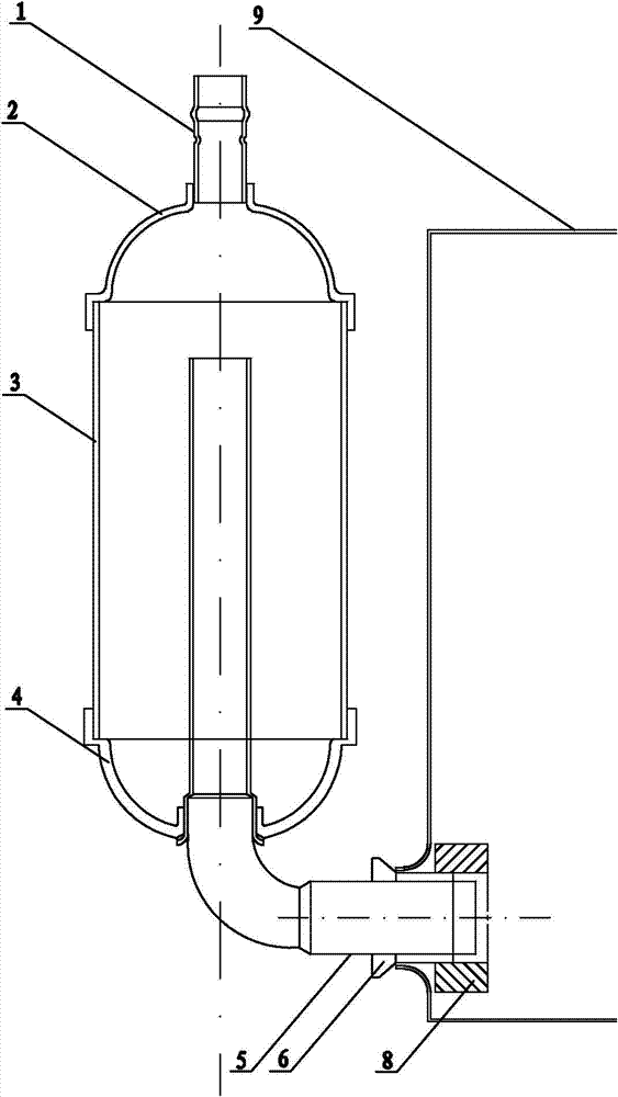
[0027] The connection structure of the cooling system of the refrigeration device in this embodiment, combined with image 3 , including a liquid receiver, a liquid separator and a compressor. The liquid separator includes an air inlet pipe 1, an upper end cover 2, a middle cylinder body 3, a lower end cover 4 and an air outlet pipe 5. One end of the air outlet pipe 5 of the liquid separator is an interference fit press into the cylinder hole 8 of the compressor, the first flange 6 is set between the air outlet pipe 5 and the compressor shell 9, and the first flange 6 is connected with the compressor shell 9 and the air outlet pipe 5 by welding; the air outlet pipe The other end of 5 is connected to the lower end cover 4, and the outlet pipe 5 and the lower end cover 4 are connected through the second flange 7, and the second flange 7, the outlet pipe 5, and the lower end cover 4 are connected by resistance welding or furnace brazing connect. Among them, interference fit In t...

Embodiment 3

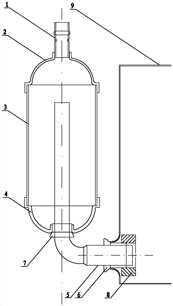
[0030] The connection structure of the cooling system of the refrigeration device in this embodiment, combined with Figure 4, including a liquid receiver, a liquid separator and a compressor. The liquid separator includes an air inlet pipe 1, an upper end cover 2, a middle cylinder body 3, a lower end cover 4 and an air outlet pipe 5. The air inlet pipe 1 passes through the third flange 10 and the upper end cover 2 connection, one end of the outlet pipe 5 of the liquid separator is pressed into the cylinder hole 8 of the compressor in the form of interference fit, the first flange 6 is set between the outlet pipe 5 and the compressor shell 9, and the first flange 6 is welded by welding. The flange 6 is connected to the compressor shell 9 and the air outlet pipe 5; the other end of the air outlet pipe 5 is connected to the lower end cover 4, and the second flange 7 is connected between the air outlet pipe 5 and the lower end cover 4, and the second flange 7 is connected to the ...


PUM


Abstract

The invention relates to a connection structure of a cooling system of a refrigerating plant, in particular to the technical field of connection relations among liquid reservoirs and liquid dispensers and among the liquid dispensers and compressors of air-conditioning cooling systems. The connection structure comprises a liquid reservoir, a liquid dispenser and a compressor. The liquid dispenser comprises an air inlet tube, an upper end cover, a middle barrel, a lower end cover and an air outlet tube, the air outlet tube of the liquid dispenser is pressed into a cylinder hole of the compressor in an interference fit manner, and a first flange is sleeved between the air outlet tube and a shell of the compressor and is connected with the shell of the compressor and the air outlet tube by means of welding. According to the technical scheme, the connection structure has the advantages of convenience in machining, simple structure and the like.

Description

technical field [0001] The invention relates to a connection structure of a cooling system of a refrigeration device, in particular to the technical field of the connection relationship between a liquid receiver and a liquid separator, and a liquid separator and a compressor in an air-conditioning cooling system. Background technique [0002] The cooling system of refrigeration devices such as air conditioners is mainly composed of liquid receivers, liquid separators and compressors connected in sequence. figure 1 , the liquid separator is mainly composed of an upper end cover 2a, a middle cylinder body 3a and a lower end cover 4a. During installation, the upper end cover 2a is connected to the liquid reservoir through the inlet pipe 1a, and the lower end cover 4a is passed through the outlet pipe 5a (also called is "reservoir elbow 5a") connected to the compressor cylinder hole 8a, after the intake pipe 1a, upper end cover 2a, middle cylinder 3a, lower end cover 4a, air out...

Claims


Application Information

Patent Timeline
Patent Type & Authority Applications(China)
IPC IPC(8): F25B41/00F25B41/40
Inventor 王志祥
Owner SHENGZHOU XINGAOLUN REFRIGERATION EQUIP
Why Eureka
Try Eureka