Ethylene cryogenic separation method for large-sized ethylene device

An ethylene plant, cryogenic separation technology, applied in the direction of cold treatment separation, refrigeration and liquefaction, liquefaction, etc., can solve the problems of manufacturing, transportation, installation difficulties, manufacturing difficulties, large size of the cold box, etc., to reduce equipment investment and operation cost, reduce the stress concentration of the nozzle, and facilitate the effect of manufacturing and transportation

Active Publication Date: 2014-01-29
PETROCHINA CO LTD +1
View PDF7 Cites 11 Cited by
  • Summary
  • Abstract
  • Description
  • Claims
  • Application Information

AI Technical Summary

Problems solved by technology

[0004] In the 1980s and 1990s, most of the ethylene technologies introduced in my country used figure 1 As shown in the complex cold box process, the cold box designed according to this has many channels, many nozzles, complex stress at the nozzles, and large dimensions, making it difficult to manufacture
In recent years, with the gradual increase in the production scale of ethylene plants, especially the construction of million-ton ethylene plants, according to figure 1 The cold box process shown will inevitably lead to a large size of the cold box, which will bring great difficulties to manufacturing, transportation, installation, etc.
The higher the complexity of the syst

Method used


Image

  • Ethylene cryogenic separation method for large-sized ethylene device
  • Ethylene cryogenic separation method for large-sized ethylene device
  • Ethylene cryogenic separation method for large-sized ethylene device

Examples


Example Embodiment

[0030] Example 1

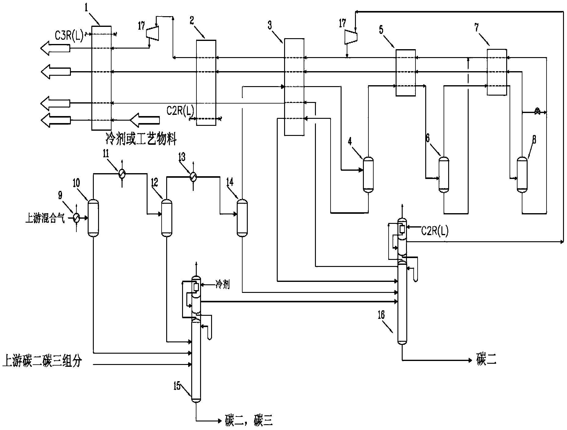
[0031] Such as image 3 As shown, the mixed gas containing C2, C3, hydrogen, and methane from the tubular cracking furnace or heavy oil catalytic cracking or coal-to-olefin process is first compressed, dried and pre-cooled to about -20°C, and then passed through a cooler 9 After cooling to about -50°C, it enters the component separation vessel 10, where the gas phase (mainly composed of carbon two, carbon one and hydrogen) and liquid phase (mainly composed of carbon one, carbon two, C3 and hydrogen), the gas phase enters the cooler 11 and is cooled to -73°C and then sent to the component separation vessel 12, and the liquid phase is sent to the pre-demethanizer 15; in the component separation vessel 12, it continues to separate into gas and liquid phases, The gas phase from the top of the component separation vessel 12 is cooled to -95°C by the cooler 13 and then enters the component separation vessel 14. The liquid phase obtained from the bottom of the compon...


PUM


Abstract

The invention relates to an ethylene cryogenic separation method for a large-sized ethylene device. The method includes the steps that mixed gas is precooled, cooled by a series of coolers and separated by a component separation container so that a gas phase and multi-strand liquid phases can be obtained; the gas phase is separated by a series of plate-fin heat exchangers and a component separation container so that a gas phase and multi-strand liquid phases can be obtained, after the pressure of liquid phase methane is reduced, cooling capacity is recycled through the heat exchangers, the liquid phase methane is conveyed to a downstream system, one of the multi-strand liquid phases and the liquid phase methane after pressure reduction are mixed, the rest of the liquid phases enter a demethanizer, and coarse hydrogen products enter the downstream system; the two firstly-coagulated liquid phases in the multi-strand liquid phases respectively enter a pre-demethanizer, and the rest of the liquid phases respectively enter the demethanizer; the pre-demethanizer separates the liquid phases into gas and liquid, the gas is delivered to the demethanizer, and the liquid is delivered to the downstream system; the demethanizer separates the gas phase into methane and C2 which are delivered to the downstream system, and the methane is delivered to the downstream system. By means of the ethylene cryogenic separation method for the large-sized ethylene device, 30% of the size of a cold box is decreased, equipment and cost are reduced, energy saving and cost reduction are achieved, and operating stability is guaranteed.

Description

technical field [0001] The invention relates to a cryogenic separation method for ethylene, in particular to a cryogenic separation method for mixed gas containing light hydrocarbon components such as C2, C3, methane and hydrogen in large-scale ethylene plants. Background technique [0002] The raw material is a mixed gas containing ethylene and propylene components obtained through tube cracking furnace cracking, heavy oil catalytic cracking or coal-to-olefins process. After cooling and separating the liquid phase, the gas phase enters the compressor to boost the pressure, and then undergoes multiple separations to finally obtain ethylene. , propylene, hydrogen, methane and other products. The function of cryogenic separation in ethylene process is to separate methane and hydrogen from the feed mixture (mainly hydrogen, methane and carbon dioxide, etc.) Since the separation principles are all based on low temperature and flash separation, and the operating temperature can ...

Claims


Application Information

Patent Timeline
IPC IPC(8): F25J3/08
CPCF25J3/0219F25J3/0233F25J3/0238F25J3/0242F25J3/0252F25J2200/74F25J2205/04F25J2210/12F25J2270/02F25J2270/04F25J2270/12F25J2270/60
Inventor 杨庆兰孙长庚辛江张来勇苏燕兵吴德娟宋磊马超凡李文堂毕可珍
Owner PETROCHINA CO LTD
Why Eureka
Try Eureka