Measuring device and method for measuring optical uniformity of optical glass
A technology of optical uniformity and optical glass, applied in the field of optical glass inspection, can solve the problems of high measurement cost and measurement difficulty, expensive interferometer, complex measurement process, etc. effect of the program
- Summary
- Abstract
- Description
- Claims
- Application Information
AI Technical Summary
Problems solved by technology
Method used
Image
Examples
Embodiment 1
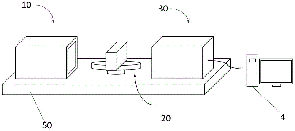
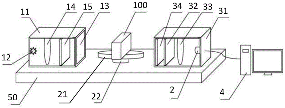
[0025] like figure 1 and figure 2 As shown, the embodiment of the present invention proposes a measuring device for the optical uniformity of optical glass. The measured optical glass has a different refractive index due to stress. The measuring device includes a light source component 10, an interference color forming component 30, and a phase compensator (not shown in the figure), CCD camera 2 and computer 4. The light source assembly 10 is composed of a light source and a polarizer and / or other basic optical devices capable of forming polarized light, and is used to polarize the light source to provide polarized light; the interference color forming assembly 30 is composed of an analyzer or other capable of making the polarized light The optical device that produces interference after birefringence is configured to make the birefringent polarized light form an interference color; the phase compensator is used to make the polarized light generate different optical path dif...
Embodiment 2
[0040] An embodiment of the present invention provides a method for measuring the optical uniformity of optical glass, the method comprising:
[0041] Step 1: Measure and record the interference color images under each optical path difference after a polarized light undergoes birefringence, including:
[0042] The method adopts the measuring device provided by the above-mentioned embodiment to measure;
[0043] Before the measurement, first check whether the measuring device is normal. The measuring method is: turn on the light source 12, light passes through each optical device in the optical path in turn, shines on the CCD camera 2, and observe whether the interference color image taken by the CCD camera 2 is displayed on the computer 40 , if the image is displayed, it means that the device is normal and can be tested. If it is unrealistic, each device in the device can be fine-tuned until the interference color image is displayed on the computer 40;
[0044] Then, the phas...
Embodiment 3
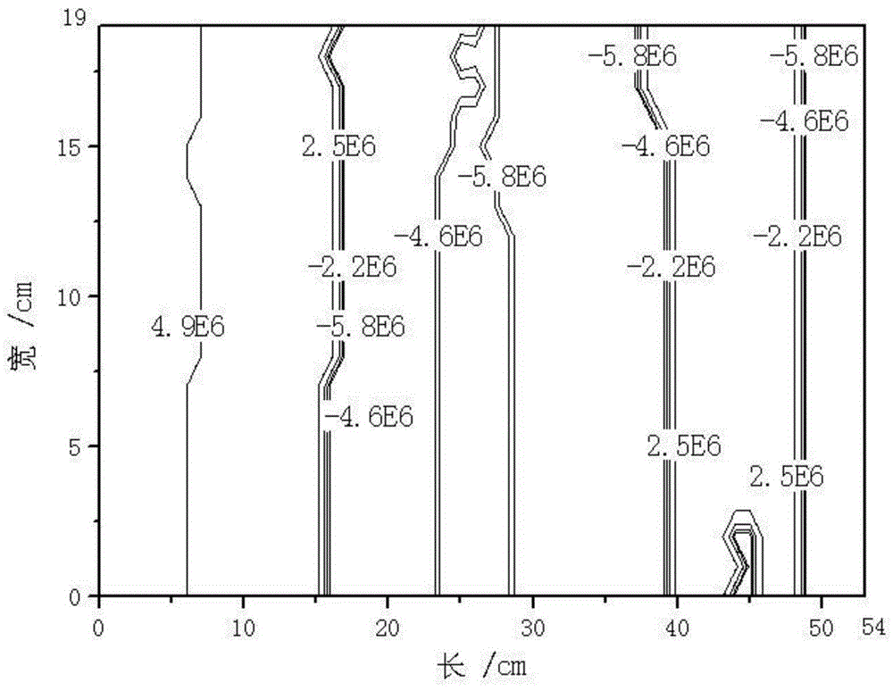
[0054] With the method that embodiment 2 provides, measure the homogeneity of an optical glass, described optical glass to be tested causes refractive index difference by stress, and this optical glass size is 54mm * 19mm, and thickness is 20mm, image 3 In order to measure the contour map of the refractive index difference of the sample, Δn can be obtained from the measurement data i The maximum value is 4.9×10 -6 , Δn i The minimum value is -5.8×10 -6 , the difference between the two is 1.17×10 -5 Therefore, the optical uniformity of this sample is 1.17×10 -5 . Additionally, from image 3 It can be seen that Δn i The distribution gradient of , so that you can intuitively see the location of poor uniformity.
PUM
 Abstract
Description
Claims
Application Information
 - R&D
- Intellectual Property
- Life Sciences
- Materials
- Tech Scout
- Unparalleled Data Quality
- Higher Quality Content
- 60% Fewer Hallucinations
Browse by: Latest US Patents, China's latest patents, Technical Efficacy Thesaurus, Application Domain, Technology Topic, Popular Technical Reports.
© 2025 PatSnap. All rights reserved.Legal|Privacy policy|Modern Slavery Act Transparency Statement|Sitemap|About US| Contact US: help@patsnap.com


