Enameled wire unwinding device

A pay-off device and enamelled technology, which is applied in the manufacture of electrical components, circuits, cables/conductors, etc., can solve the problem that the tension sheave cannot provide constant tension, and achieve diameter increase, stable tension, and easy pay-off tension Effect

Active Publication Date: 2014-01-29
WUXI XIZHOU MAGNET WIRES
View PDF3 Cites 5 Cited by
  • Summary
  • Abstract
  • Description
  • Claims
  • Application Information

AI Technical Summary

Problems solved by technology

[0003] In view of the above problems, the present invention provides an enameled wire pay-off device, which has a simple structure, can move the equipment flexibly, and improves the problem that the existing tension sheave cannot provide constant tension because the tension sheave is too small, thereby affecting the quality of the enameled wire, and can realize The use of pay-off reels of different specifications avoids the limitations of production

Method used


Image

  • Enameled wire unwinding device
  • Enameled wire unwinding device
  • Enameled wire unwinding device

Examples


Embodiment Construction

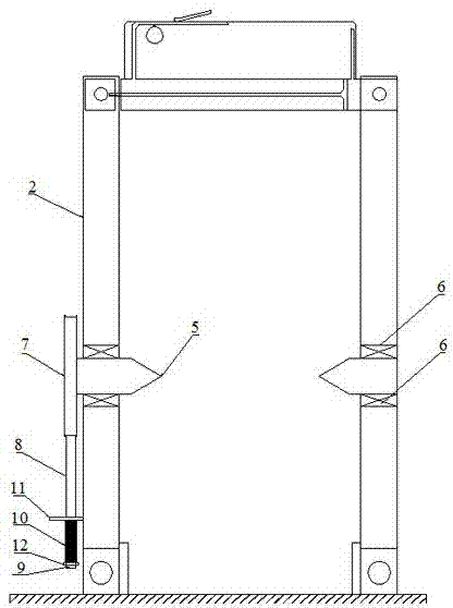
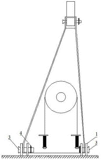
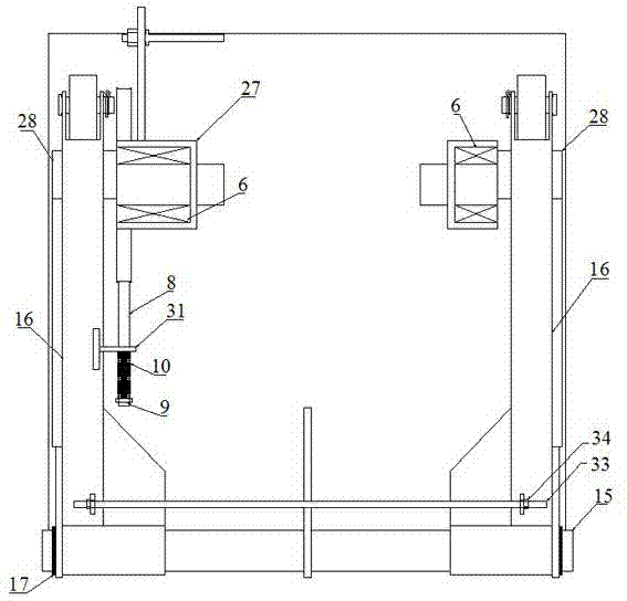
[0011] Such as image 3 , Figure 4 As shown, the present invention includes a tension sheave 7 and a damping band 8. The end of the damping band 8 placed on the tension sheave 7 is connected to the screw one 9. The diameter of the tension sheave 7 is 35cm~40cm, and the bracket two 13 is welded on One end of the base plate 14, the shaft 15 passes through the junction of the bracket two 13 and the support arm 16 and is positioned by the snap spring one 17, the ear plate one 18 is welded on the support arm 16, and one end of the cable-stayed support 19 cooperates with the pin 3 and the cotter pin 4 It is connected and fixed on the ear plate one 18, and the support column 20 is provided with a pin hole 21, and one end of the support column 20 is connected and fixed to the end of the support arm 16 through the pin hole 21, the pin 3 and the cotter pin 4. The support column 20, the cable-stayed support 22 The other end is connected and fixed to the ear plate 2 23 through the coope...


PUM

PropertyMeasurementUnit
diameteraaaaaaaaaa

Abstract

The invention provides an enameled wire unwinding device which is simple in structure. By the enameled wire unwinding device, equipment can be flexibly moved, the problem that quality of enameled wires is affected by incapability of providing constant tension due to excessively small size of existing tension sheaves is solved, use of unwinding discs with different specifications can be realized, and limitation of production is avoided.

Description

technical field [0001] The invention relates to the technical field of enameled production line equipment, in particular to an enamelled wire pay-off device. Background technique [0002] The wire pay-off process is the first procedure of the enameled wire production line. The stability of the wire pay-off and the tension control have a certain influence on the quality of the enameled wire, such as figure 1 , figure 2 As shown, the base 1 in the existing enamelled pay-off device is fixed on the ground, the bottom of the bracket 2 is connected to the base 1 through the pin 3 and fixed by the cotter pin 4, and the tapered clamp 5 is embedded in the bracket 1 through the bearing 6. In 2, the tension sheave 7 is welded to the tapered fixture 5 on one side, the end of the damping band 8 that is set on the tension sheave 7 is connected to the screw one 9, and the spring 10 is set on the screw one 9 and stuck in the slot On 11, draw-in groove 11 is welded on support-2, and nut-...

Claims


Application Information

Patent Timeline
Patent Type & Authority Applications(China)
IPC IPC(8): H01B13/00
Inventor 曹永义陈晓东周里
Owner WUXI XIZHOU MAGNET WIRES
Why Eureka
Try Eureka