Sunflower type solid antenna capable of being spread

A fancy, solid technology, used in antennas, folded antennas, electrical components and other directions, can solve problems such as low accuracy and limited operating frequency, and achieve the effect of ensuring synchronization, reducing degrees of freedom, and high profile accuracy

Inactive Publication Date: 2014-01-29
HARBIN INST OF TECH
View PDF1 Cites 16 Cited by
  • Summary
  • Abstract
  • Description
  • Claims
  • Application Information

AI Technical Summary

Problems solved by technology

[0004] In order to solve the problems of low surface precision and limited operating frequency of the current mesh and inflatable antennas, the present invention further proposes a sun fancy solid expandable antenna

Method used


Image

  • Sunflower type solid antenna capable of being spread
  • Sunflower type solid antenna capable of being spread
  • Sunflower type solid antenna capable of being spread

Examples


specific Embodiment approach 1

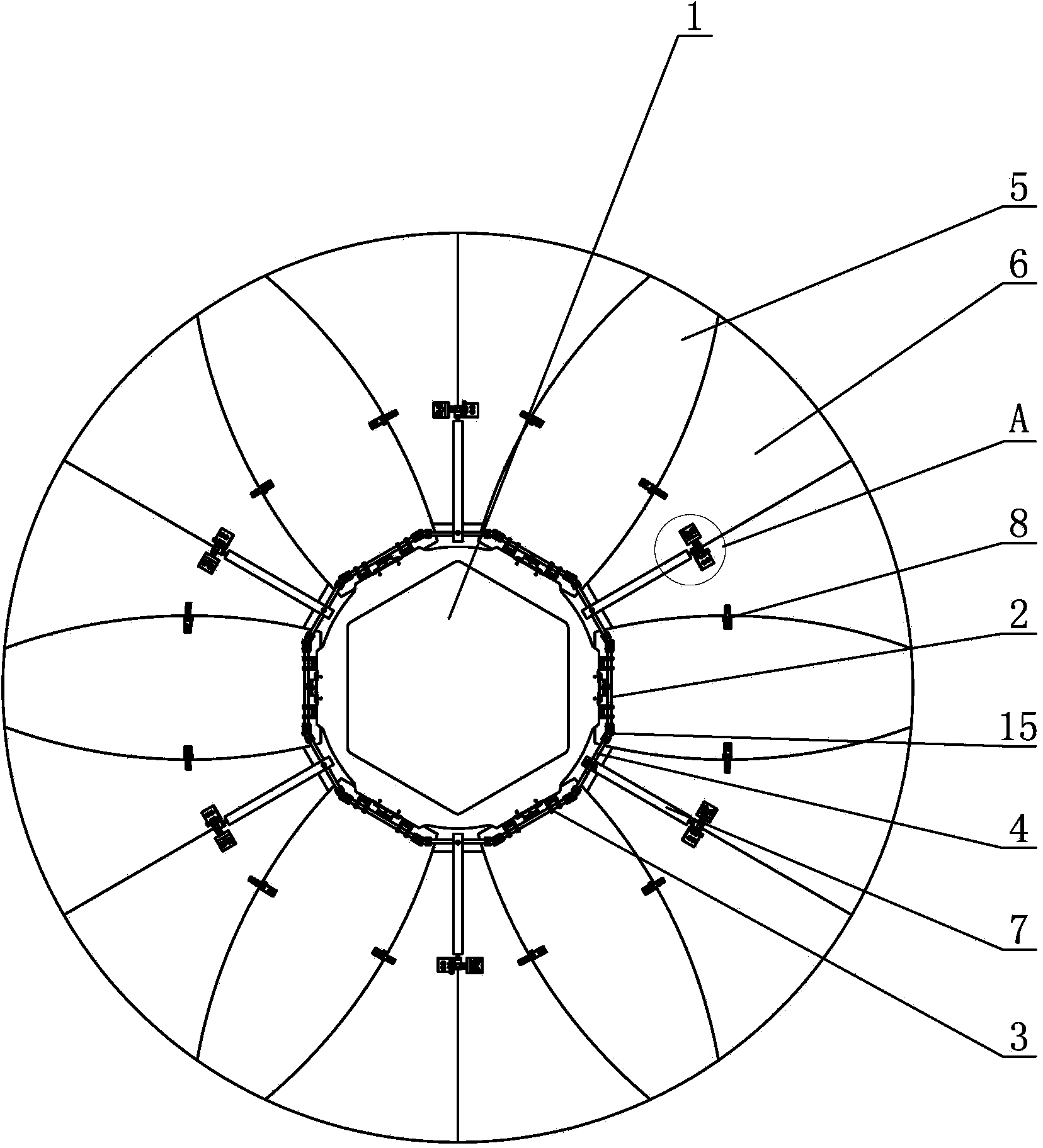
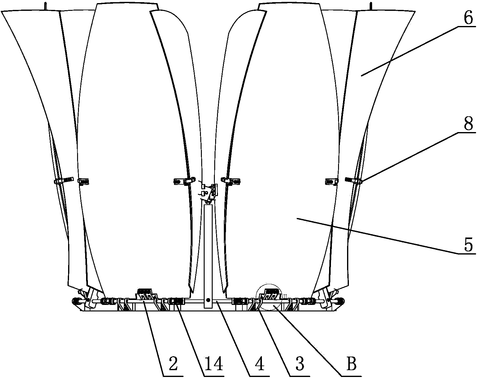
[0008] Specific implementation mode one: combine Figure 1 to Figure 7 Describe this embodiment, a sunflower-style solid deployable antenna described in this embodiment includes a base 1, six drive shafts 2, six drive shaft brackets 3, six cardan shafts 4, and six main spherical shell parts 5. Twelve auxiliary spherical shell parts 6, six connecting rods 7, twelve main hinges 8 and multiple spherical hinge mechanisms, the base 1 is a regular dodecagonal plate body, six drive shafts 2 and six The universal shafts 4 are staggered along the edge of the base 1, and the axis of each drive shaft 2 is parallel to the corresponding side of the base 1, and the axis of each universal shaft 4 is parallel to the corresponding side of the base 1. One side is parallel, and each drive shaft 2 is respectively connected to the corresponding side on the base 1 through a drive shaft bracket 3, and the two ends of each drive shaft 2 are respectively connected to one end of an adjacent cardan shaf...

specific Embodiment approach 2

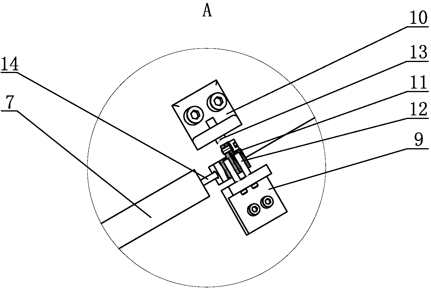
[0009] Specific implementation mode two: combination figure 1 and figure 2 To illustrate this embodiment, each spherical hinge mechanism of a sunflower-style solid deployable antenna in this embodiment includes a first hinge seat 9 of a secondary spherical shell, a second hinge seat 10 of a secondary spherical shell, and a hinge connection Block 11, the first hinge lever 12 of the two secondary spherical shell parts, the second hinge lever 13 of the secondary spherical shell part and the connecting rod hinge lever 14, the first hinge seat 9 of the secondary spherical shell part passes through the first hinge of the two secondary spherical shell parts The rod 12 is connected with the hinge connecting block 11, the second hinge seat 10 of the auxiliary spherical shell part is connected with the hinge connecting block 11 through the second hinge rod 13 of the auxiliary spherical shell part, and the hinge connecting block 11 is connected with the corresponding one through the con...

specific Embodiment approach 3

[0011] Specific implementation mode three: combination figure 1 , image 3 , Figure 4 , Figure 6 and Figure 7 To illustrate this embodiment, both ends of each gimbal shaft 4 of the sunflower-style solid deployable antenna described in this embodiment are respectively connected to one end of the adjacent driving shaft 2 through a universal joint 15 .

[0012] The technical effect of this embodiment is: so arranged that the drive shaft 2 and the cardan shaft are connected into a dodecagonal closed structure, so that the torque applied by the drive device to the structure is equally and simultaneously transmitted to each ball joint mechanism On, and then act on the two sub-disks connected to it, to ensure the synchronization of deployment. Other compositions and connections are the same as those in Embodiment 1 or 2.


PUM


Abstract

The invention provides a sunflower type solid antenna capable of being spread. The sunflower type solid antenna capable of being spread aims at resolving the problems that mesh type and inflatable antenna molded surfaces are not high in precision and limited in working frequency at preset. According to the sunflower type solid antenna capable of being spread, a regular dodecagon plate body serves as a base, six driving shafts and six universal shafts are arranged in a staggered mode along the edge of the base, each driving shaft is connected with a corresponding edge on the base through the corresponding driving shaft support, the two ends of each driving shaft are respectively connected with one end of an adjacent universal shaft, each driving shaft is connected with the lower end of a main spherical shell, the other side of each auxiliary spherical shell is connected with the other side of an adjacent auxiliary spherical shell through a spherical hinge mechanism, the middle of each universal shaft is connected with the lower end of a connecting rod, and the upper end of each connecting rod is connected with the corresponding spherical hinge mechanism. The sunflower type solid antenna capable of being spread is used for the field of antennas.

Description

technical field [0001] The invention relates to an antenna, in particular to a sunflower-style solid expandable antenna. Background technique [0002] The development of aerospace industry is an important part of my country's long-term scientific and technological development plan. Many major aerospace science and technology projects in my country are closely related to space expandable structures. At present, deployable antennas are widely used in military, aerospace, information and other fields. With the development of science and technology, large-aperture, high-precision, and light-weight deployable antennas are becoming the development trend of deployable antennas. [0003] According to the material of the working surface, the deployable antenna can be simply divided into three categories: network type, air-filled type and solid reflector type. The main disadvantages of the first two antennas are that the surface accuracy is not high enough and the working frequency ...

Claims


Application Information

Patent Timeline
Patent Type & Authority Applications(China)
IPC IPC(8): H01Q1/08H01Q15/16
Inventor 邓宗全李忠杰郭宏伟刘荣强
Owner HARBIN INST OF TECH
Why Eureka
Try Eureka