Supercharge Your Innovation With Domain-Expert AI Agents!

Wireless charging position calibration method and electronic equipment

A technology of wireless charging and electronic equipment, applied in the field of communication, can solve problems such as being unable to find a suitable charging signal

Inactive Publication Date: 2014-01-29
SHENZHEN TINNO WIRELESS TECH
View PDF2 Cites 17 Cited by
  • Summary
  • Abstract
  • Description
  • Claims
  • Application Information

AI Technical Summary

Problems solved by technology

When users use wireless charging technology to charge, they often have the problem of not being able to find the location of a suitable charging signal

Method used


Image

  • Wireless charging position calibration method and electronic equipment
  • Wireless charging position calibration method and electronic equipment
  • Wireless charging position calibration method and electronic equipment

Examples


Embodiment 1

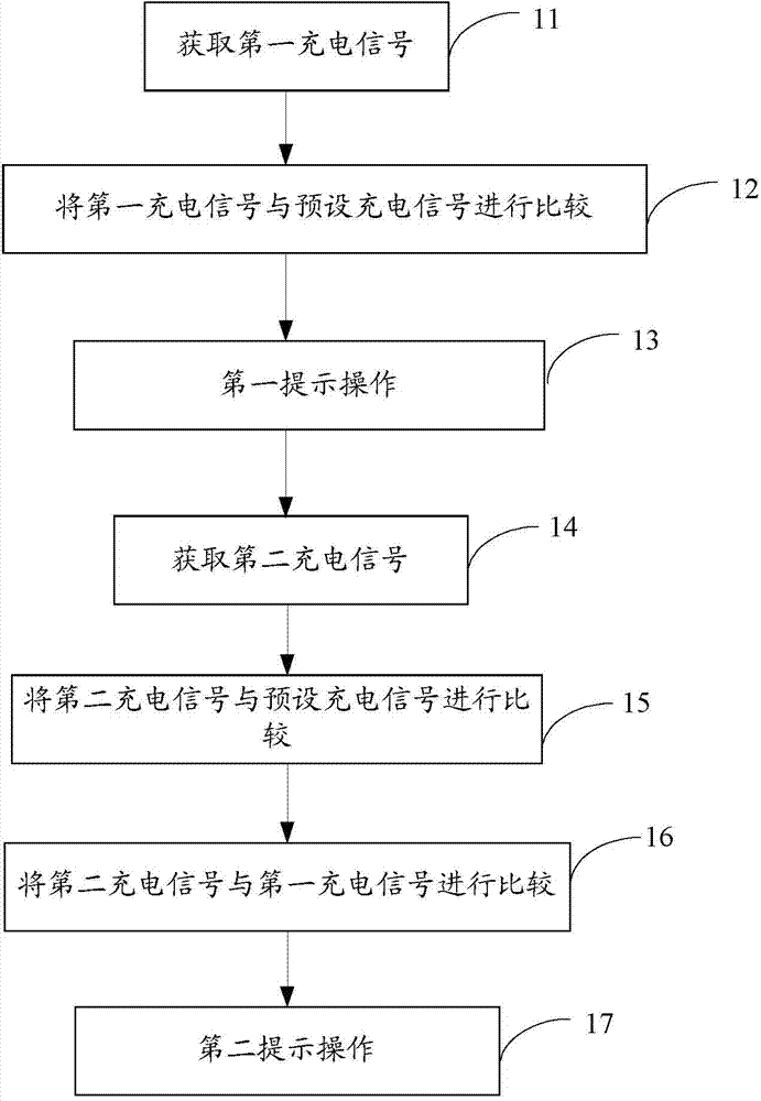
[0035] Please refer to figure 1 , figure 1 It is a flow chart of an embodiment of a method for calibrating a wireless charging position of an electronic device.

[0036] In this embodiment, the method for calibrating the wireless charging position of an electronic device includes:

[0037] 11: In the wireless charging state, acquire a first charging signal representing the signal strength of the electronic device performing wireless charging at the initial position.

[0038] The electronic device is placed on the wireless charging device. After the wireless charging function is turned on, the wireless charging device charges the electronic device. Because the types and shapes of the charged devices are different, it is not possible to directly determine which position has the best wireless charging position and the highest charging intensity. It can be charged most efficiently, so after the electronic device is placed on the wireless charging device, in the wireless charging...

Embodiment 2

[0079] Generally, the receiving sensor of wireless charging is connected to the main circuit of the electronic device through two contacts (positive and negative) to charge the battery system. The wired charging of most electronic devices adopts the general-purpose Micro USB interface, which can be charged through ordinary USB chargers or computer USB interfaces. Most of the wireless charging contacts are connected to the wired USB interface of the main circuit in parallel. When the user inserts the wired charging of the USB interface during wireless charging, the related circuits may be burned due to the difference in voltage and current between the two. Therefore, the design of this embodiment An automatic detection circuit for wired and wireless charging channels eliminates the hidden danger of parallel connections.

[0080] Please refer to Figure 6~7 , Figure 6 It is a structural block diagram of an electronic device embodiment of the present application, Figure 7 It...


PUM


Abstract

The invention discloses a wireless charging position calibration method. The method includes under a wireless charging state, acquiring a first charging signal; comparing the first charging signal with a preset charging signal; if the former is smaller than the later, outputting a first prompting message; acquiring a second charging signal; comparing the second charging signal with the preset charging signal; if the second charging signal is smaller than the preset charging signal, comparing the second charging signal with the first charging signal, and outputting a second prompting message according to a comparison result. The invention further provides a device used for wireless charging position calibration and electronic equipment. By the method, in the process of wireless charging of the electronic equipment, the electronic equipment can be moved freely according to indication of wireless charging signals of the electronic equipment, and direction of moving of the electronic equipment with bigger charging current is acquired according to operation instructions, for randomly moving the electronic equipment, of a user.

Description

technical field [0001] The present application relates to the communication field, and in particular to a wireless charging position calibration method and electronic equipment. Background technique [0002] As a new technology, wireless charging has been rapidly applied in mobile phones and various digital products. Through the matching wireless charging stand, point-to-point wireless charging can be realized, so that people can get rid of the shackles of wires, and wirelessly charge mobile phones and mobile devices conveniently and quickly. [0003] Wireless charging technology utilizes the principle of electromagnetic induction and AC induction technology, uses coil coupling at the sending and receiving ends to send and receive the AC signals generated by induction, rectifies the AC power, and outputs the stabilized voltage to charge mobile phones and mobile devices. The wireless charging stand has strict position matching requirements with the mobile device. When users...

Claims


Application Information

Patent Timeline
IPC IPC(8): H02J7/00H02J17/00H02J50/90
Inventor 何震宇夏俊稳
Owner SHENZHEN TINNO WIRELESS TECH
Features
  • R&D
  • Intellectual Property
  • Life Sciences
  • Materials
  • Tech Scout
  • Unparalleled Data Quality
  • Higher Quality Content
  • 60% Fewer Hallucinations
Learn More