Uplink data transmitting and receiving method and equipment in time division duplex system

A data transmission method and time-division duplex technology, which are applied in the direction of preventing/detecting errors through diversity reception, transmission systems, digital transmission systems, etc., and can solve problems such as damaged uplink coverage, inability to support TTIbundling, and limited coverage.

Active Publication Date: 2014-01-29
DATANG MOBILE COMM EQUIP CO LTD
View PDF4 Cites 8 Cited by
  • Summary
  • Abstract
  • Description
  • Claims
  • Application Information

AI Technical Summary

Problems solved by technology

[0009] First, only three uplink and downlink configurations (that is, uplink and downlink configurations 0, 1, and 6) support TTI bundling, and other uplink and downlink configurations cannot support TTI bundling, resulting in limited uplink coverage;
[0010] Second, the three uplink and downlink configurations that support TTI bundling adopt a unified bundling size, which does not optimize the number of uplink subframes for each uplink and downlink co

Method used


Image

  • Uplink data transmitting and receiving method and equipment in time division duplex system
  • Uplink data transmitting and receiving method and equipment in time division duplex system
  • Uplink data transmitting and receiving method and equipment in time division duplex system

Examples


Embodiment 1

[0082] Embodiment 1: configure 0 for TDD uplink and downlink;

Embodiment 11

[0083] Embodiment 1.1: Distributed (that is, N uplink subframes are N non-contiguous uplink subframes);

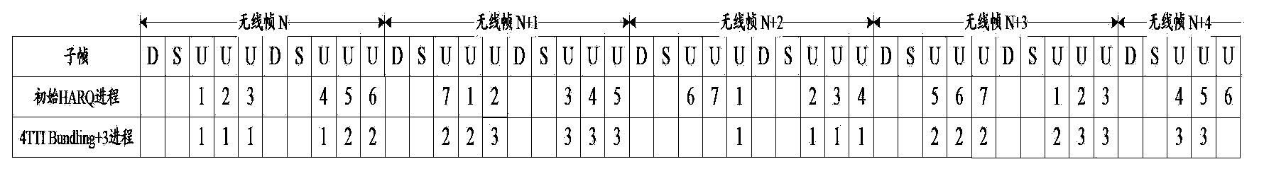
[0084] N=6, its transmission pattern is as follows Figure 6A shown.

[0085] Base station side:

[0086] Step 1: The base station receives the RV0-RV2-RV3-RV1-RV0- RV2.

[0087] Step 2: The base station sends PHICH information (ie ACK / NACK indication) on the 6th subframe in the radio frame n+2;

[0088] Further, the base station can also send PDCCH DCI format0 (ie UL grant signaling) on ​​the 6th subframe in the radio frame n+2, where the LSB is set to 1 or 1 PHICH =1; or, the base station sends the PDCCH DCI format0 on the 7th subframe in the radio frame n+2, where the MSB is set to 1 or 1 PHICH =0; the base station can also use high-level signaling to semi-persistently schedule uplink data.

[0089]Step 3: The base station receives the RV0-RV2-RV3-RV1- RV0-RV2 or RV3-RV1-RV0-RV2-RV3-RV1, or RV0-RV2-RV3-RV1-RV0-RV2 for new TB.

[0090] Terminal side:

[0091] St...

Embodiment 21

[0095] Embodiment 2.1: Centralized (that is, N uplink subframes are N consecutive uplink subframes);

[0096] N=6, its transmission pattern is as follows Figure 6A shown.

[0097] Base station side:

[0098] Step 1: The base station receives RV0-RV2-RV3-RV1-RV0-RV2 of the same TB on the 3rd, 4th, 5th, 8th, 9th, and 10th uplink subframes in the radio frame n.

[0099] Step 2: The base station sends PHICH information on the 6th subframe in the radio frame n+1;

[0100] Further, the base station can also send the PDCCH DCI format0 on the 6th subframe in the radio frame n+2, in which the LSB is set to 1 or 1 PHICH =1; or send PDCCH DCI format0 on the 7th subframe in radio frame n+2, where the MSB is set to 1 or 1 PHICH =0; the base station can also use high-level signaling to semi-persistently schedule uplink data.

[0101] Step 3: The base station receives the RV0-RV2-RV3-RV1-RV0-RV2 or RV3-RV1- RV0-RV2-RV3-RV1, or RV0-RV2-RV3-RV1-RV0-RV2 for new TB.

[0102] Terminal sid...


PUM


Abstract

A method and an apparatus for uplink data transmission and reception in time division duplex are disclosed in the embodiments of the present invention, relating to the field of wireless communication, which are used for increasing the utilization of uplink sub-frame and lifting the uplink covering effect. In the present invention, the terminals transmit the redundancy versions of transport blocks by bundling N uplink sub-frames, and the base stations receive the redundancy versions of transport blocks, wherein N refers to the number of uplink sub-frame in a wireless frame. The invention makes full use of uplink sub-frame and further improves the uplink covering effect.

Description

technical field [0001] The invention relates to the field of wireless communication, in particular to a method and device for sending and receiving uplink data in a time division duplex system. Background technique [0002] In the Long Term Evolution (LTE) system, limited by the maximum transmit power of the terminal (User Equipment, UE), the power available for each data packet within a transmission time interval (Transmission Time Interval, TTI) is very small. Limited, therefore, uplink transmission cannot meet the performance requirements under bad channel conditions. In order to improve uplink coverage, the LTE system adopts TTI bundling (bundling) technology, and it is expected to at least achieve the performance of High Speed ​​Uplink Packet Access (HSUPA). The so-called TTI bundling technology is that the UE sends multiple redundancy versions (Redundancy Version, RV) of the same data transmission block (Transport Block, TB) in multiple subframes after channel coding ...

Claims


Application Information

Patent Timeline
IPC IPC(8): H04L1/00H04L1/06H04L1/18
CPCH04L1/1819H04L1/1887
Inventor 徐婧拉盖施潘学明
Owner DATANG MOBILE COMM EQUIP CO LTD
Why Eureka
Try Eureka