Power control method, UE (user equipment) and network equipment
A technology for power control and network equipment, applied in the field of communication, can solve problems such as difficult power control effectively, and achieve the effect of ensuring QoS characteristics and avoiding radiation exceeding the standard
- Summary
- Abstract
- Description
- Claims
- Application Information
AI Technical Summary
Problems solved by technology
Method used
Image
Examples
no. 1 example
[0042] see figure 2 , is the first embodiment of the power control method of the present invention, which shows the process of performing power control on the UE side:
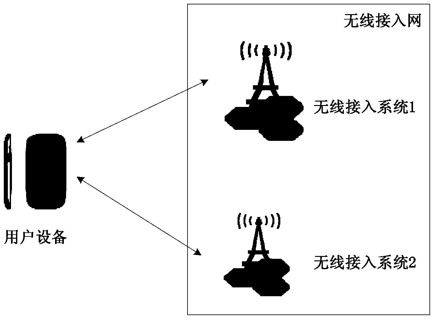
[0043] Step 201: The UE acquires an aggregated uplink transmit power parameter value, where the aggregated uplink transmit power parameter value is a power parameter value when the UE accesses at least two systems simultaneously.
[0044]Wherein, the UE may configure the aggregated maximum output power as the aggregated uplink transmit power parameter value according to the uplink maximum output power of each system accessing at least two systems, and the aggregated maximum output power is not less than the maximum uplink output power of a single system The maximum value is not greater than the sum of the maximum uplink output power of each system; the aggregate maximum output power can be used as the RF (Radio Frequency, radio frequency) capability of the UE, that is, the aggregate maximum output power can b...
no. 1 example
[0168] see Figure 10 , which is a block diagram of the first embodiment of the UE of the present invention:
[0169] The UE includes: a first obtaining unit 1010 and a first control unit 1020 .
[0170] Wherein, the first acquiring unit 1010 is configured to acquire an aggregated uplink transmit power parameter value, where the aggregated uplink transmit power parameter value is a power parameter value when the UE accesses at least two systems at the same time;
[0171] The first control unit 1020 is configured to control power when the UE accesses the at least two systems according to the aggregated uplink transmit power parameter value.
[0172] Specifically, the first acquisition unit 1010 may include ( Figure 10 not shown):
[0173] The first parameter acquisition subunit is configured to acquire at least one of the following parameters: the UE configures the aggregated maximum output power as the first parameter according to the uplink maximum output power of each sy...
no. 2 example
[0178] see Figure 11 , is a block diagram of the second embodiment of the UE of the present invention:
[0179] The UE includes: a first obtaining unit 1110 , a priority obtaining unit 1120 and a first control unit 1130 .
[0180]Wherein, the first obtaining unit 1110 is configured to obtain an aggregated uplink transmission power parameter value, where the aggregated uplink transmission power parameter value is a power parameter value when the UE accesses at least two systems at the same time;
[0181] The priority obtaining unit 1120 is configured to obtain the power control priority for different systems configured by the network device or configured by the UE;
[0182] The first control unit 1130 is configured to control power for accessing the at least two systems according to the aggregated uplink transmit power parameter value and the power control priority.
[0183] Specifically, the first acquiring unit 1110 may include ( Figure 11 not shown):
[0184] The first...
PUM
 Abstract
Description
Claims
Application Information
 - R&D
- Intellectual Property
- Life Sciences
- Materials
- Tech Scout
- Unparalleled Data Quality
- Higher Quality Content
- 60% Fewer Hallucinations
Browse by: Latest US Patents, China's latest patents, Technical Efficacy Thesaurus, Application Domain, Technology Topic, Popular Technical Reports.
© 2025 PatSnap. All rights reserved.Legal|Privacy policy|Modern Slavery Act Transparency Statement|Sitemap|About US| Contact US: help@patsnap.com


