
An oil-pneumatic balance suspension and its hydraulic control system for multi-axle heavy vehicles

A technology for balancing suspensions and heavy-duty vehicles, which is applied in the direction of suspensions, interconnection systems, elastic suspensions, etc., and can solve the problems that the piston rod is easily polluted and difficult to be cleaned automatically, so as to avoid being easily polluted and improve the reliability of use Effect

Inactive Publication Date: 2015-12-02
HUAZHONG UNIV OF SCI & TECH
View PDF9 Cites 0 Cited by
  • Summary
  • Abstract
  • Description
  • Claims
  • Application Information

AI Technical Summary

Problems solved by technology

[0005] Aiming at the above defects or improvement needs of the prior art, the present invention provides an oil-pneumatic balance suspension for multi-axle heavy vehicles and its hydraulic control system, wherein the built-in oil-pneumatic spring of the air chamber is adjusted by combining the characteristics of the multi-axle heavy vehicles. The new design of its hydraulic control system can effectively avoid the disadvantage that the piston rod is easily polluted and difficult to clean automatically when the oil-gas spring rod cavity is arranged above, and at the same time, it is convenient to realize the height adjustment of the vehicle body and the independent lifting of the axle, so it is especially suitable for various Class multi-axle heavy vehicles for transport purposes

Method used


Image

  • An oil-pneumatic balance suspension and its hydraulic control system for multi-axle heavy vehicles
  • An oil-pneumatic balance suspension and its hydraulic control system for multi-axle heavy vehicles
  • An oil-pneumatic balance suspension and its hydraulic control system for multi-axle heavy vehicles

Examples


Embodiment Construction

[0030] In order to make the object, technical solution and advantages of the present invention clearer, the present invention will be further described in detail below in conjunction with the accompanying drawings and embodiments. It should be understood that the specific embodiments described here are only used to explain the present invention, not to limit the present invention. In addition, the technical features involved in the various embodiments of the present invention described below may be combined with each other as long as they do not constitute a conflict with each other.

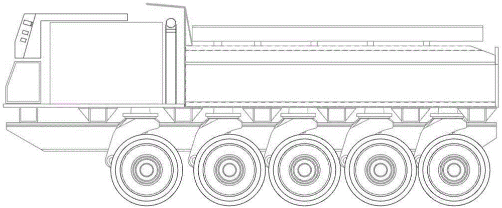
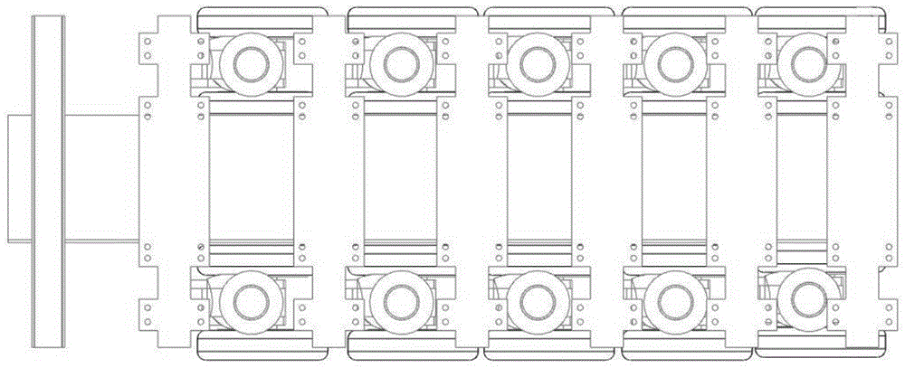
[0031] Figure 1a It is an exemplary installation diagram of the oil-air balance suspension according to the present invention when it is used for a five-axle heavy-duty vehicle, Figure 1b yes Figure 1a A schematic diagram of the general arrangement of the oil-air balanced suspension shown in . Such as Figure 1a and 1b As shown in , considering the performance requirements of the vehicle and ...


PUM


Abstract

The invention discloses an oil-gas balanced suspension used for a multi-axle heavy vehicle, which comprises an upper rotating arm, an oil-gas spring and a lower swinging arm, wherein for an oil-gas spring of a key component, the oil-gas balanced suspension comprises a cylinder barrel, a hollow piston rod and upper and lower connecting bodies; the upper and lower connecting bodies are connected to the upper rotating arm and axles respectively through a joint bearing; the piston at the upper end of the hollow piston rod is internally provided with a damping hole and a one-way valve to form a valve assembly; the lower end of the piston rod is fixedly connected to the lower connecting body through a screw thread to form a piston rod component and separate the cylinder barrel into a no-rod cavity at the upper end and a rod cavity at the lower end; the hollow piston rod is internally and fixedly provided with a built-in oil-gas cylinder; a floating piston in the oil-gas cylinder divides the oil-gas cylinder into an upper inner gas chamber and a lower inner oil chamber. The invention also discloses a corresponding hydraulic control system. Through the invention, the disadvantages that the piston rod is easily polluted and is hard to be cleaned automatically can be avoided efficiently, and convenience is brought to realization of the height adjustment of the vehicle body and independent improvement of the axles.

Description

technical field [0001] The invention belongs to the technical field of vehicle suspension, and more specifically relates to an oil-air balance suspension for a multi-axle heavy vehicle and a hydraulic control system thereof. Background technique [0002] The function of the oil-pneumatic balance suspension is to connect the frame with the axle, transmit the force and moment acting between the axle and the frame, and use the joint action of the accumulator and the hydraulic shock absorber to buffer the uneven road surface and transmit it to the frame. The impact force of the vehicle can attenuate the vibration of the vehicle body caused by the uneven road surface, thus improving the ride comfort of the vehicle. The oil-air balance suspension can also ensure that the axle loads of the connected axles are equal, so it is widely used in special vehicles and off-road vehicles. [0003] Existing oil-pneumatic spring suspensions generally include two types, one is an oil-pneumatic...

Claims


Application Information

Patent Timeline
Patent Type & Authority Patents(China)
IPC IPC(8): B60G17/04B60G17/033
Inventor 唐新蓬陶亚松马少群刘坤任姗星肖智灵
Owner HUAZHONG UNIV OF SCI & TECH
Learn More