Bottom trough refractory material composite structure of aluminium cell cathode carbon block and manufacturing method thereof

A refractory material and cathode carbon block technology, applied in the field of aluminum electrolytic cells, can solve the problems of inability to ensure complete and in-place installation, and achieve the effects of reducing resistance, increasing conductive area, and reducing horizontal current.

Inactive Publication Date: 2014-02-05
NORTHEASTERN UNIV LIAONING
View PDF4 Cites 2 Cited by
  • Summary
  • Abstract
  • Description
  • Claims
  • Application Information

AI Technical Summary

Problems solved by technology

Yet when using this patented technology, when the cathode carbon block that this cathode steel rod bottom is stretched out the cathode carbon block bottom surface is placed on the anti-seepage material or the refractory brick on the tank liner surface that has built flat, just ran into difficulty
Even using impermeable refractory materials with powdery properties cannot guarantee its complete installation and proper installation

Method used


Image

  • Bottom trough refractory material composite structure of aluminium cell cathode carbon block and manufacturing method thereof

Examples


Embodiment 1

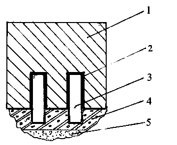
[0023] like figure 1 As shown, a combination structure of a tank-shaped refractory material for an aluminum electrolytic cell, including a cathode steel rod 3 protruding from the bottom surface of the cathode carbon block 1 and a refractory material at the bottom of the aluminum electrolytic cell, the cathode steel Between the rod 3 and the cathode carbon block 1 is a carbon tamping paste 2, and the upper surface of the refractory material is provided with a groove structure coupled with the cathode steel rod protruding from the bottom of the cathode carbon block 1, that is, the groove structure refractory material 4. The lower part of the channel structure refractory material 4 is an anti-seepage material layer 5 .

[0024] The manufacturing method of the trough-shaped refractory composite structure of the aluminum electrolytic cell is carried out according to the following steps:

[0025] First, construct the anti-seepage material layer 5 at the bottom of the aluminum elect...

Embodiment 2

[0030] The channel structure refractory structure 4 coupled with the cathode steel rod 3 protruding from the bottom of the cathode carbon block 1 of the aluminum electrolytic cell described in this embodiment is a prefabricated integral refractory material.

[0031] First, prefabricate an integral trough-shaped refractory structure 4 that can be tightly coupled with the surface of the bottom 1 of the cathode carbon block and the cathode steel rod 3 protruding from the bottom surface of the cathode carbon block 1 by pouring or tamping or other methods;

[0032] Afterwards, the prefabricated integral trough-type refractory structure 4 is assembled with the cathode carbon block 1 with cathode steel rod 3 protruding at the bottom;

[0033] Finally, the combined structure of the cathode carbon block 1, the cathode steel rod 3 and the trough-shaped refractory structure 4 is hoisted as a whole on the anti-seepage material at the bottom of the aluminum electrolytic cell or possibly oth...


PUM


Abstract

The invention relates to the technical field of an aluminium cell, and particularly relates to a bottom trough refractory material composite structure of an aluminium cell cathode carbon block and a manufacturing method thereof. The bottom trough refractory material composite structure comprises a trough refractory material structure body, wherein the structure body tightly contacts the bottom surface of the cathode carbon block and the surface of a cathode steel rod body protruding on the bottom surface of the cathode carbon block; a groove coupled to the cathode steel rod body part protruding on the bottom surface of the cathode carbon block is formed on the upper surface of the structure body; an anti-seepage layer is arranged at the lower part of the structure body. The manufacturing method comprises the following steps: building the anti-seepage layer and the trough structure refractory material and installing the cathode carbon block, or firstly combining the overall refractory material structure with the cathode carbon block, and then putting the overall combined body on the anti-seepage layer at the bottom of the trough refractory material or other types of thermal insulation materials. By adopting the technical scheme disclosed by the invention, under the condition of not increasing the height of the cathode carbon block, the conductive area of the cathode steel rod can be increased, the resistance of the cathode steel rod is reduced, and the horizontal current in cathode molten aluminum of the aluminium cell is also reduced.

Description

technical field [0001] The invention belongs to the technical field of aluminum electrolytic cells, and in particular relates to a combination structure of refractory materials at the bottom of a cathode carbon block of an aluminum electrolytic cell and a manufacturing method. Background technique [0002] Energy saving is the core technical content of industrial aluminum electrolytic production. The energy saving of industrial aluminum electrolytic cell production can be achieved by increasing the current efficiency, or by increasing and reducing the cell voltage without the current efficiency being greatly affected. All of these methods and techniques can also be achieved through the stability of the electrolytic cell cathode aluminum liquid level. There are many ways to improve the stability of the cathode aluminum liquid level of the electrolytic cell, and one of the most important measures is to reduce the horizontal current in the cathode aluminum liquid of the electro...

Claims


Application Information

Patent Timeline
Patent Type & Authority Applications(China)
IPC IPC(8): C25C3/08
Inventor 彭建平冯乃祥
Owner NORTHEASTERN UNIV LIAONING
Why Eureka
Try Eureka