Construction method of spiral cone extruded soil pile

A construction method and a technology of soil-squeezing piles, which are applied in the fields of earth drilling, sheet pile walls, and foundation structure engineering, can solve problems such as the inability to apply hard ground, reduce the bearing capacity of piles, and form false screw teeth, etc., to achieve pile formation The quality is controllable and reliable, the pile bearing capacity is high, and the effect of saving raw materials

Active Publication Date: 2015-08-12
吉林省大星基础工程科技有限公司
View PDF5 Cites 0 Cited by
  • Summary
  • Abstract
  • Description
  • Claims
  • Application Information

AI Technical Summary

Problems solved by technology

Screw piles require high technology for synchronous control of pile-forming equipment. For the uncertainty and non-uniformity of soil layer and soft and hard changes, it is difficult to ensure that the pile-forming rock and soil screw teeth do not flex, and false screw teeth will be formed. Reduce the bearing capacity of the pile and cannot be applied to hard ground
The two-way spiral extruded pile adopts the hole-forming method of drilling first and then extruding. During the down-rotation drilling process, the soil is drilled out by using the cylindrical auger bit part of the two-way helical extruding and expanding drill bit, and transported from bottom to top by the helical blades. To the part of the cone core tube, the soil is gradually squeezed into the side wall of the pile hole through the cone core tube. In complex strata such as clay and gravel layers, the rock and soil produced by rotary drilling will block the transportation path formed by the spiral blades, and it is easy to cause the drilling phenomenon; The stability between the stratum and the extruded soil is poor, and there will be a collapse phenomenon, which will seriously bury the drill

Method used


Image

  • Construction method of spiral cone extruded soil pile
  • Construction method of spiral cone extruded soil pile
  • Construction method of spiral cone extruded soil pile

Examples


Embodiment 1

[0029] Example 1 Construction Method of Spiral Cone Squeeze Pile

[0030] (1) Spiral Cone Soil Squeeze Bit

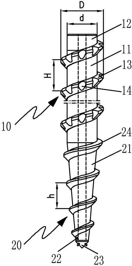
[0031] Such as figure 1 As shown, the spiral cone soil-extruding drill bit is composed of a spiral cylinder structure (10) and a spiral cone structure (20) to form an integrated structure.

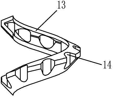
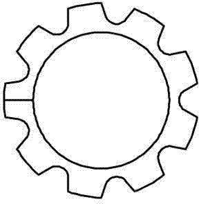
[0032] The spiral cylinder structure (10) is: a drill joint (12) is provided at one end of the cylinder core tube (11), and a spiral cylinder blade (13) is provided on the outer edge of the cylinder core tube (11). Such as Figure 2-3 As shown, several notches (14) are evenly provided on the helical cylinder blade (13). Such as Figure 6 As shown, the cross-section of the helical cylinder blade (13) is quadrilateral, and the included angles between the two sides and the cylinder core tube (11) are φ=45-50° and ω=65-70° respectively. Spiral cylinder blade (13) is the blade of equal height. The distance H=350~420mm between the helical cylinder blades (13). The diameter D of...


PUM


Abstract

The invention relates to a construction method of a spiral cone soil squeezing pile and a spiral cone soil squeezing drill bit. It is a kind of extrusion and expansion directly in the rock and soil layer, so as to avoid the collapse in the pile hole due to poor extrusion and expansion stability between different rock and soil layers. The hole forming of the present invention is through the high-torque power head, the pressurizing device, the standard drill rod and the spiral cone soil-extruding drill bit, which are rotated clockwise downward and drilled, and the lower part of the cone structure in the spiral cone soil-extruding drill bit is formed in the rock. The soil layer is directly squeezed and expanded to drill the hole, which is the main soil squeezed part, and the upper part of the column structure is used to assist the soil squeeze to ensure that the hole diameter and the hole do not collapse; The expanded hole is squeezed and expanded again to prevent diameter shrinkage. At the same time of top-spin lifting, start the concrete delivery pump to press the pile material into the pile hole. The method of the invention has higher bearing capacity, smaller settlement, better pile quality, lower cost, less energy consumption, higher work efficiency, more environmental protection, and can be used for construction operations under various geological conditions.

Description

technical field [0001] The invention relates to a construction method of a spiral cone soil squeezing pile and a spiral cone soil squeezing drill bit used in the field of civil engineering. Background technique [0002] In the field of building foundation construction, pile foundation pile formation methods can be divided into soil-discharging piles and non-soil-discharging piles. [0003] Construction methods such as long helix CFG, percussion drilling and rotary drilling, etc., have the disadvantages of low pile bearing capacity, high cost and high cost of cleaning and dumping and waste mud. [0004] There are two types of non-drainage piles: prefabricated piles and cast-in-place piles. Prefabricated piles have the disadvantages of expensive manufacturing equipment, high production cost, long pile body, difficult transportation, and are only suitable for soft soil layers and small pile diameters. Cast-in-place piles include screw piles and two-way spiral extruded and exp...

Claims


Application Information

Patent Timeline
Patent Type & Authority Patents(China)
IPC IPC(8): E02D5/36E21B10/44
Inventor 刘守进赵立杰薛淑华郭海艳王国岐路守园张桂芳鲁春新赵景双
Owner 吉林省大星基础工程科技有限公司
Why Eureka
Try Eureka