Displacement pile and construction method and drilling tool thereof

A construction method and technology for extruding soil piles, applied in the field of extruding soil piles, can solve the problems of increasing the difficulty and progress of pile-forming construction, blocking the transportation passage, affecting the construction progress, etc., achieving novel structure, not easy to hold back drilling, and high pile bearing capacity. Effect

Inactive Publication Date: 2016-10-26
刘录怀
View PDF11 Cites 4 Cited by
  • Summary
  • Abstract
  • Description
  • Claims
  • Application Information

AI Technical Summary

Problems solved by technology

The main problem is that the soil is rotary excavated first, then transported upwards and then squeezed to the pile walls on both sides, so the rotated soil will block the transportation path formed by the rotating blades, and it is easy to cause the drilling phenomenon
Moreover, the discharged soil or mud increases the difficulty and progress of pile construction.
[0003] The announcement number (CN103556628A), the Chinese patent on the publication date (2014-02-05), discloses a construction method of a spiral vertebral soil extruding pile. Good, high efficiency, but in the actual pile construction process, its overall spiral cone structure will cause the soil in the pile to be unscrewed, and the muck needs to be transported outside, which affects the progress of the construction

Method used


Image

  • Displacement pile and construction method and drilling tool thereof
  • Displacement pile and construction method and drilling tool thereof
  • Displacement pile and construction method and drilling tool thereof

Examples


Embodiment Construction

[0018] The present invention will be described in detail below in conjunction with the accompanying drawings and specific embodiments.

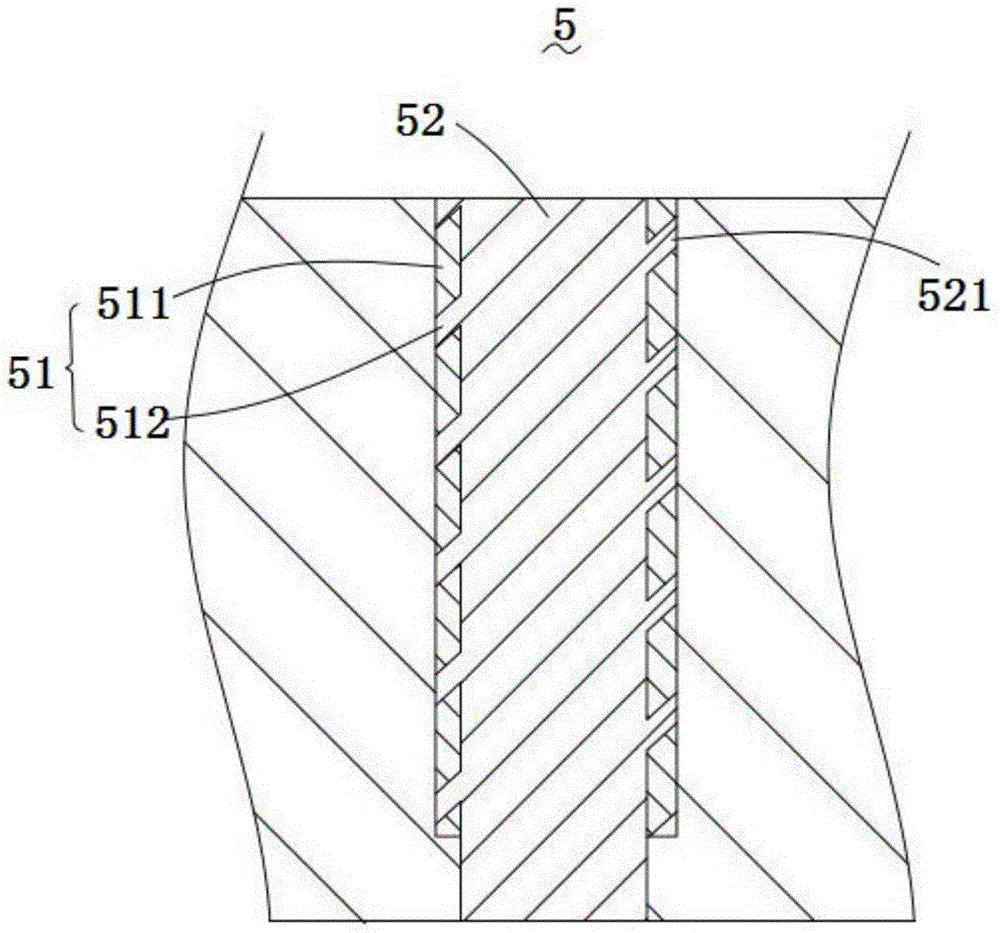
[0019] A soil-squeezing pile with a structure such as figure 1 As shown, it includes a soil squeezing part 5, and the soil squeezing part 5 includes a pile foundation 51 and a concrete pile body 52 filled in the pile foundation 51. The inner thread 512 on the inner wall of the squeezed soil layer 511, the concrete pile body 52 includes an outer thread 521 formed on its outer wall, and the inner thread 512 is screwed to the outer thread 521.

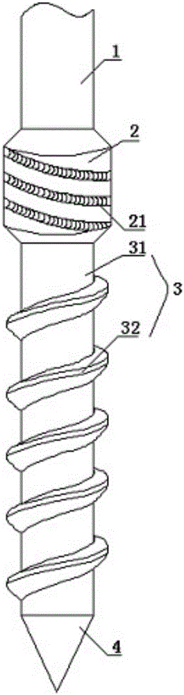
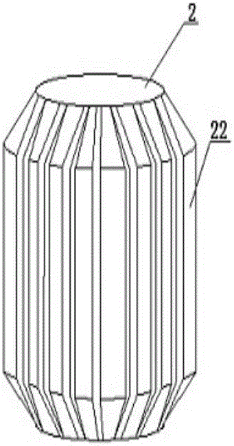
[0020] The utility model relates to a drilling tool for forming piles by squeezing soil, the structure of which is as follows: figure 2 , image 3 As shown, it includes a linear cylindrical structure 1, a concrete blocking ring 2, a spiral cylindrical structure 3 and a drill bit 4, and the cylindrical structure 1, the concrete blocking ring 2 and the spiral cylindrical structure 3 are sequentially fix...


PUM


Abstract

The invention discloses a displacement pile and a construction method and drilling tool thereof. The drilling tool comprises a linear cylinder structure, a concrete blocking ring, a spiral column structure and a drill bit. The cylinder structure, the concrete blocking ring and the spiral column structure are connected fixedly and sequentially to form the integrated drilling tool. The spiral column structure comprises a cylinder pipe core and a spiral blade clockwise arranged at the outer edge of the cylinder pipe core. The cylinder pipe core is connected with the drill bit through a drill bit connector arranged at the lower end of the cylinder pipe core. The height ratio of the concrete blocking ring to the spiral column structure is 7:25, and the edge of the outer wall of the concrete blocking ring is flush with the edge of the outer wall of the spiral blade. The drilling tool is novel in structure, the pile forming quality is good, bit bouncing is not liable to occur, and environmental protection is achieved. In addition, according to the construction method of the displacement pile, in the pile forming process, a concrete blocking ring structure blocks soil from being screwed out, and the pile is formed directly through extruding and expanding. The formed pile is high in bearing capacity, good in pile forming quality, and the work efficiency is further improved.

Description

technical field [0001] The invention belongs to the technical field of civil engineering, and in particular relates to a soil-squeezing pile, a construction method of the soil-squeezing pile and a drilling tool thereof. Background technique [0002] At present, in foundation projects such as construction, water conservancy, and highways, double-helix extruded piles are currently the most commonly used form of pile foundation. The soil that is drilled out of the hole will be squeezed into the side wall of the pile hole, and then the two-way helical closed extrusion drill bit will move upwards and rotate again to squeeze and expand the pile hole. Squeeze into the side wall of the pile hole, and start the concrete pump to press the pile material into the pile hole while the topspin is lifted. The main problem is that the soil is rotary excavated first, then transported upwards and then squeezed to the pile walls on both sides. Therefore, the rotated soil will block the transpo...

Claims


Application Information

Patent Timeline
Patent Type & Authority Applications(China)
IPC IPC(8): E02D5/36E21B10/32E21B17/22
CPCE02D5/36E21B10/327E21B17/22
Inventor 刘录怀
Owner 刘录怀
Why Eureka
Try Eureka