
Exhaust valve assembly of hydraulic transmission pipeline of clutch

A technology of hydraulic transmission and exhaust valve, used in fluid pressure actuating devices, servo motor components, mechanical equipment, etc., can solve the problems of slow oil filling, air residue, poor clutch separation, etc., to improve accuracy The effect of degree and reliability

Active Publication Date: 2014-02-05
SINO TRUK JINAN POWER
View PDF8 Cites 2 Cited by
  • Summary
  • Abstract
  • Description
  • Claims
  • Application Information

AI Technical Summary

Problems solved by technology

In fact, there are often no conditions during vehicle repair and maintenance. The oil filling speed is slow, and there is more air in the pipeline, which causes the clutch to disengage badly.
For large passenger cars, due to the long hydraulic pipeline, it is difficult to arrange the hydraulic pipeline in an ideal way with the middle low and the two ends high

Method used


Image

  • Exhaust valve assembly of hydraulic transmission pipeline of clutch
  • Exhaust valve assembly of hydraulic transmission pipeline of clutch
  • Exhaust valve assembly of hydraulic transmission pipeline of clutch

Examples


Embodiment Construction

[0019] Selected embodiments of the present invention are now explained with reference to the accompanying drawings. The following descriptions of the embodiments of the present invention disclosed by those skilled in the art are only exemplary and not intended to limit the solutions of the present invention.

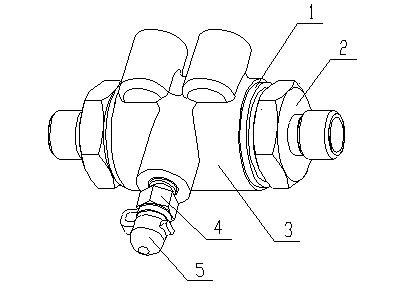
[0020] Reference attached figure 1 , a clutch hydraulic transmission pipeline exhaust valve assembly, including a valve body 3, two joint bodies 2, two sealing washers 1, air release screw 4 and dust cap 5.

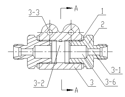
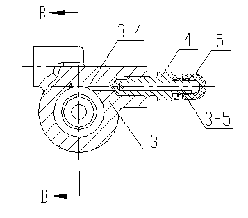
[0021] Reference attached figure 2 , The valve body 3 is a cylindrical body with a through hole inside to form a hollow structure, and an internal thread is provided near the outside of the through hole. The joint body 2 is used to connect the hydraulic oil circuit; there is a stepped through hole in the center of the joint body 2, the stepped through hole includes the inner hole 3-6 and the oil hole 3-1, and the diameter of the inner hole 3-6 is larger than that ...


PUM


Abstract

The invention provides an exhaust valve assembly of a hydraulic transmission pipeline of a clutch, and the exhaust valve assembly can be used for removing the air in the hydraulic transmission pipeline of the clutch. The exhaust valve assembly of the hydraulic transmission pipeline of the clutch comprises a valve body, two joint bodies, two sealing washers, an air collection chamber, an exhaust hole and an air bleed screw, wherein the interior of the valve body has a hollow structure; the two joint bodies are used for connecting a hydraulic circuit, are respectively provided with an oil hole and are respectively arranged at the two sides of the valve body; the two sealing washers are arranged between the valve body and the joint bodies; the air collection chamber is arranged at the upper part of an inner cavity of the valve body and at the upper parts of the joint bodies; the exhaust hole is formed in the valve body and at the upper part of the air collection chamber, and is communicated with the outside of the valve body; the air bleed screw is arranged on the exhaust hole.

Description

technical field [0001] The invention relates to a clutch hydraulic transmission pipeline exhaust device, in particular to a clutch hydraulic transmission pipeline exhaust valve assembly. Background technique [0002] The clutch control system of medium-sized and large passenger cars and trucks with a total weight of more than 2 tons generally adopts hydraulic transmission. When the hydraulic transmission system is filled with transmission oil, air will inevitably enter the pipeline. The slower the oil is filled, the more air will enter. At the same time, the movement of the master pump piston in some structures will generate air bubbles, and some air bubbles will enter the pipeline. The air in the line will occupy the effective volume of the transmission fluid, causing the clutch to not disengage. Since the clutch-operated hydraulic transmission is a discontinuous transmission, the air flow in the pipeline has a certain range, and it is difficult to discharge from the clutc...

Claims


Application Information

Patent Timeline
IPC IPC(8): F15B13/02
Inventor 许佳成范彩红李文君崔慧萍张子强薛秋生杨国玉
Owner SINO TRUK JINAN POWER
Learn More