

Rotary kiln barrel mounting method
An installation method and technology of rotary kiln, which can be used in rotary drum furnaces, furnaces, lighting and heating equipment, etc., can solve the problems of increased human and material resources, long time consumption, etc., and achieve the effect of reducing investment, shortening construction period and obvious advantages.
- Summary
- Abstract
- Description
- Claims
- Application Information
AI Technical Summary
Problems solved by technology
Method used
Image

Examples
Embodiment 1
[0033] A method for installing a rotary kiln shell described in this embodiment includes the following installation steps:
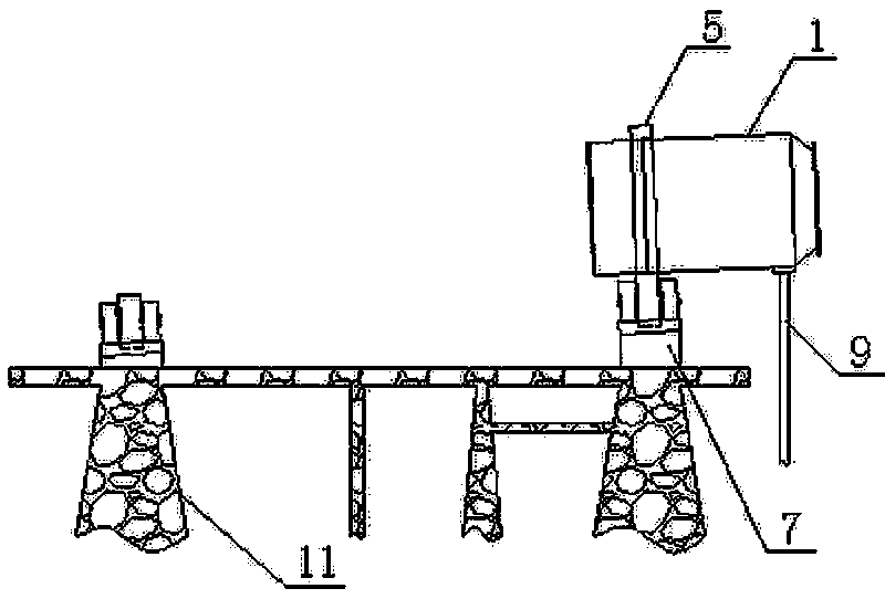
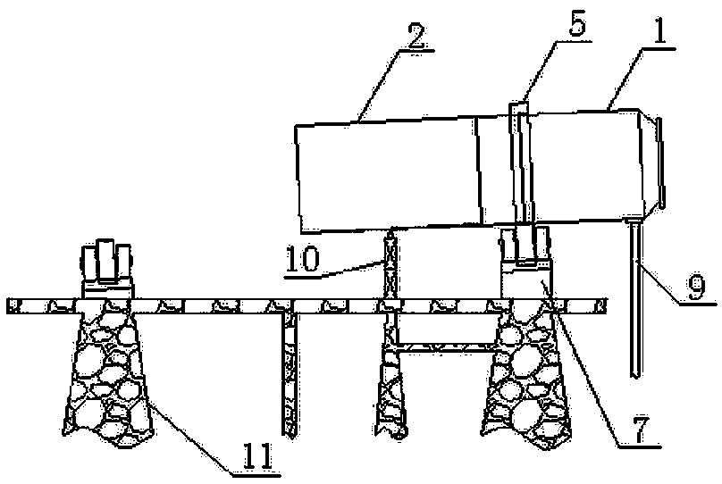
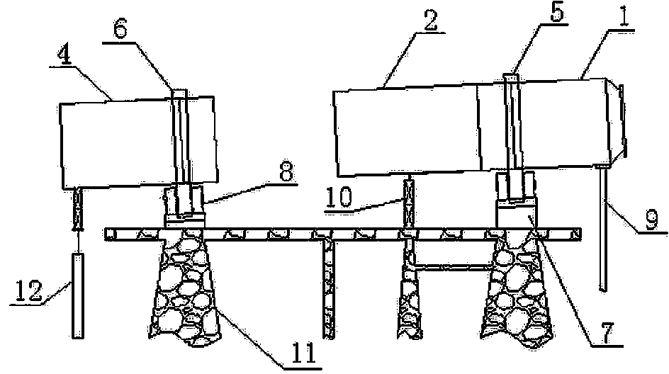
[0034] first step, such as figure 1 As shown, first, install the kiln tail section cylinder body, that is, the first section cylinder body. The specific installation process is to set two supporting devices on the concrete platform 11, which are respectively used to support the kiln tail section cylinder body 1. The support device 7 and the second support device 8 for supporting the kiln head section cylinder body 4 are provided on the outside of the concrete platform 11 for carrying the first steel support frame 9 for carrying the tail of the kiln tail section cylinder body 1, and the kiln tail section cylinder body 1 Lift to the corresponding installation location for installation. The method for installing the kiln tail section cylinder in the present invention is the same as the traditional method, and the structures involved are all exis...
Embodiment 2
[0042] In order to solve the installation problem of the first rolling ring 5, this embodiment, on the basis of the embodiment 1, places an arc steel bracket on the first supporting device 7 before installing the kiln tail section cylinder 1 to carry the kiln. The height of the cylinder body 1 in the tail section is greater than the thickness of the first rolling ring 5. After the first rolling ring 5 is installed, the cylinder body 1 in the tail section of the kiln is lifted up by a jack, and the arc steel bracket is taken out. Lower the jack so that the weight of the first rolling ring 5 and the kiln tail section shell 1 is all borne on the first support device 7 and the first steel support frame 9 . The traditional first rolling ring 5 is relatively difficult to install and will take a certain amount of time, because the diameter of the first rolling ring 5 is only slightly larger than the diameter of the kiln tail section cylinder 1, and the kiln tail section cylinder...
Embodiment 3
[0044] In this embodiment, on the basis of Example 1, four stoppers are respectively installed on the kiln tail section shell 1 on both sides of the first rolling ring 5, and the relative positions of the first rolling ring 5 and the kiln tail section shell 1 Fixed to prevent the displacement of the first rolling ring 5 during the operation of the rotary kiln. The spot welding is a temporary fixation. After the rotary kiln shell is completely adjusted and welded, the first rolling ring 5 and the kiln tail section shell 1 are finely adjusted. For the relative device, weld all the stoppers and the backing plate on the cylinder firmly.
PUM
 Abstract
Description
Claims
Application Information