Supercharge Your Innovation With Domain-Expert AI Agents!

A combination fixture and method for improving the manufacturing and processing efficiency of small transformers

A combination fixture and transformer technology, applied in the manufacture of inductors/transformers/magnets, electrical components, circuits, etc., can solve the problems of orderly placement of transformers, accumulation of materials in the dispensing section, low efficiency, etc., to ensure consistency Sex and workmanship quality, reduce processing time, and reduce production cost

Active Publication Date: 2015-10-28
金升阳(怀化)科技有限公司
View PDF5 Cites 0 Cited by
  • Summary
  • Abstract
  • Description
  • Claims
  • Application Information

AI Technical Summary

Problems solved by technology

[0013] 2. Since the test action in the test section is relatively simple, it will inevitably cause material accumulation in the dispensing section, which seriously affects the takt time and overall efficiency of the transformer production line
[0014] 3. The transformers flow down on the conveyor belt one by one. If the transformers cannot be placed in an orderly manner, they will appear scattered, so it is difficult to match the corresponding automatic dispensing equipment.
[0015] 4. Transformer immersion operation is inefficient and requires employees to deal with them one by one, which is inefficient
The depth of impregnation cannot be guaranteed consistently, so that the quality of transformer impregnation cannot be effectively guaranteed

Method used


Image

  • A combination fixture and method for improving the manufacturing and processing efficiency of small transformers
  • A combination fixture and method for improving the manufacturing and processing efficiency of small transformers
  • A combination fixture and method for improving the manufacturing and processing efficiency of small transformers

Examples


Embodiment Construction

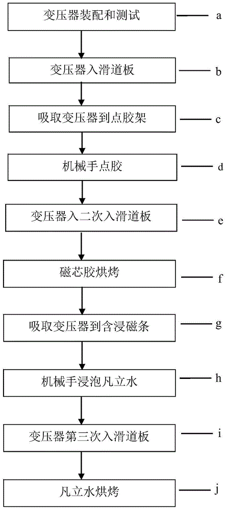
[0073] The combined jig of the present invention will be described in detail below with reference to schematic diagrams.

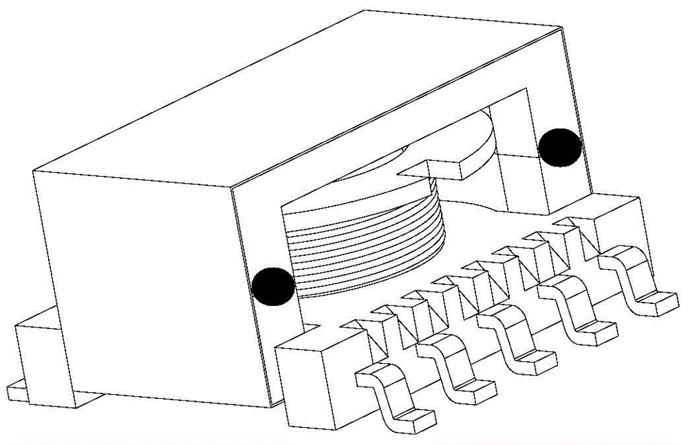
[0074] like Figure 4 , Figure 4a , Figure 5 As shown, the chute plate 20 adopts a rectangular alloy plate with light weight and high strength. There are multiple slideways excavated on the front of the board, and each slideway is provided with two slots with different widths and depths. The wider and shallower wide slot 23 is used for sliding into the transformer in the test section. The object is the two rows of pins of the transformer, so the width B of the slot is wider and shallower. The narrower and deeper narrow groove 22 is used to remove the transformer at the back end of the dispensing section. The bearing of the slideway is the magnetic core surface at the top of the transformer, so its width A is narrower and deeper; the narrow groove 22 is located at the end of the wide groove 23. middle.

[0075] In order to slide into the transformer ...


PUM


Abstract

The invention discloses a combined jig for improving a manufacturing efficiency of a small-sized transformer. The combined jig comprises a sliding trough plate, a glue dispensing strip, and a varnish containing and immerging strip, wherein multiple sliding ways are formed in the front side of the sliding trough plate; two trough positions are formed in each sliding way; one trough position is a wide trough used for bearing two rows of pins of the transformer while the other trough position is a narrow trough used for bearing a magnetic core surface at the top part of the transformer; a trough position used for adsorbing the magnetic core at the top part of the transformer is formed in the front side of the glue dispensing strip; an embedding position where a magnet is fixed is formed in the backside, and handles are arranged at the two ends of the magnet strip; the varnish containing and immerging strip has the structure similar to that of the glue dispensing strip. With the utilization of the combined jig, the transformer can be switched rapidly in a manufacturing procedure; through the glue dispensing strip and the varnish containing and immerging strip, semi-automation of glue dispensing and varnish immersion of the transformer can be realized, and the glue dispensing and varnish operation of the transformer is changed from single operation to batch operation. Therefore, production efficiency of ER type transformers is increased greatly, and cost is saved.

Description

technical field [0001] The invention relates to a combined jig for improving the manufacturing efficiency of a small transformer; the invention also relates to a method for manufacturing an electronic transformer using the combined jig. Background technique [0002] As we all know, the common SMD (Surface Mounted Devices abbreviation) series electronic transformers made of ER small magnetic cores such as ER7.5, ER11.5, ER14. Processing, low cost and other characteristics, widely used in high power density, highly integrated power supply occasions, especially in DC-DC low-power power supply modules as power transformers. Most of the transformers using the above-mentioned ER magnetic cores still adopt the traditional skeleton structure, which is cumbersome and inefficient in the manufacturing process. If a fully automatic production line is used, it will lead to poor compatibility and huge risk of investment. At the same time, the industry will also carry out auxiliary equipm...

Claims


Application Information

Patent Timeline
Patent Type & Authority Patents(China)
IPC IPC(8): H01F41/00
Inventor 谢赤述向宇峰
Owner 金升阳(怀化)科技有限公司
Features
  • R&D
  • Intellectual Property
  • Life Sciences
  • Materials
  • Tech Scout
  • Unparalleled Data Quality
  • Higher Quality Content
  • 60% Fewer Hallucinations
Learn More