Keeper for implant, assembly thereof, and method for affixing keeper

A positioning piece and assembly technology, which is used in dental implants, fasteners, medical science, etc., can solve the problems of loose positioning piece 110, reduced tension, small contact area, etc. staggered effect

Inactive Publication Date: 2014-02-05
HITACHI METALS LTD
View PDF6 Cites 14 Cited by
  • Summary
  • Abstract
  • Description
  • Claims
  • Application Information

AI Technical Summary

Problems solved by technology

However, in the denture fitting of U.S. Patent No. 6,709,270, since the contact area between the front end portion of the ring portion 137 and the upper end portion of the implant body 110 is small, the tension decreases due to the plastic deformation of the ring portion 137 during long-term use. , so that the slack of the positioning member 110 may be generated

Method used


Image

  • Keeper for implant, assembly thereof, and method for affixing keeper
  • Keeper for implant, assembly thereof, and method for affixing keeper
  • Keeper for implant, assembly thereof, and method for affixing keeper

Examples


no. 1 approach

[0048] (a) structure

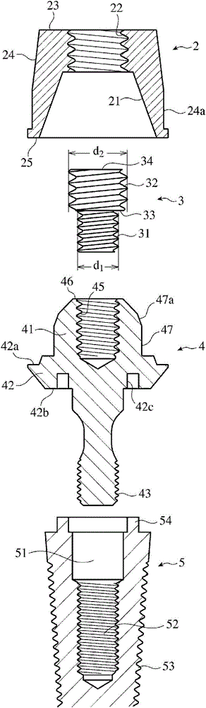
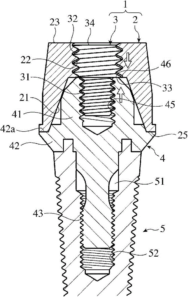
[0049] exist figure 1 and figure 2 The implant positioning tool and its assembly according to the first embodiment of the present invention are shown in . The locator assembly for implantation fixed to the implant body 5 has an abutment 4 and a locator 1 screwed to the implant body 5, and the locator 1 includes: a locator body 2 with a threaded hole 22; The threaded hole 22 of 2 and the threaded hole 45 of the head portion 41 of the abutment 4 are screwed into the two-stage threaded member 3 .

[0050] The implant body 5 is a cylindrical member having an external thread portion 53 on the outer peripheral surface for embedding in the jawbone, and has: a central hole 51 for inserting the lower external thread portion 43 of the abutment 4; An internally threaded portion 52 provided on the inner side of the portion 51 and screwed with the externally threaded portion 43 ; The implant body 5 preferably has an outer diameter (about 3 to 6.5 mm) and a leng...

no. 3 approach

[0073] exist Figure 13 and Figure 14 , shows the implant keeper and its assembly according to the third embodiment of the present invention. This implant keeper assembly includes an abutment 7 screwed to an implant body 5 using a screw 8 , and a keeper 1 fastened to a head portion 71 of the abutment 7 . The positioning part 1 is composed of a positioning part main body 2 and a two-stage threaded member 6 . The structure of the positioning member 1 and the implant body 5 itself is the same as that of the second embodiment.

[0074] The abutment 7 has: a head 71 engaged with the locator main body 2; an enlarged diameter portion 72 connected to the lower end of the head 71; coaxially communicating with a through hole 77 extending in the head 71, and extending from the enlarged diameter The cylindrical part 73 protrudes from the lower surface 72b of the part 72. The upper surface outer peripheral portion 72 a of the enlarged diameter portion 72 is in contact with the bottom ...


PUM


Abstract

A keeper for an implant is provided with: (a) a keeper body consisting of a soft magnetic material, the keeper body having a recess which receives the head of an abutment which has a female thread section and also having a female thread section which is provided along the center axis so as to communicate with the recess and which has a greater nominal diameter than the female thread section of the abutment; and (b) a two-stage threaded member having a small-diameter threaded section which engages with the female thread section of the abutment and also having a large-diameter threaded section which engages with the female thread section of the keeper body. The keeper for an implant is characterized in that, when the keeper body is rotated in the engaging direction after the small-diameter threaded section is engaged with the female thread section of the abutment and the large-diameter threaded section is engaged with the female thread section of the keeper body, the keeper body is firmly fastened to the abutment by the two-stage threaded member.

Description

technical field [0001] The invention relates to an implant positioning piece for fixing a magnetic fitting for dentures to an implant body, an assembly thereof, and a fixing method for the positioning piece. Background technique [0002] In recent years, in the treatment of dental implants, in order to make the dentures easy to assemble and disassemble, the following method is mostly adopted: a positioning piece made of soft magnetic material is fixed on the implant body embedded in the jawbone, and a positioning piece is fixed on the positioning piece. Magnetizes denture accessories that have built-in magnets. [0003] U.S. Patent No. 6709270 discloses a magnetic dental accessory, such as Figure 15 As shown, the denture fitting 105 with a built-in magnet 155 is magnetized on the positioning member 103 made of soft magnetic material screwed to the implant body 110 . The positioning member 103 has: a conical tapered part 135 provided at the upper part; and a ring part 137 p...

Claims


Application Information

Patent Timeline
Patent Type & Authority Applications(China)
IPC IPC(8): A61C8/00A61C13/235
CPCA61C8/0059A61C8/0068A61C19/02A61C8/0069A61C8/005A61C8/0013A61C8/00A61C8/0074A61C8/0081A61C13/235A61C8/0053
Inventor 菊地亮
Owner HITACHI METALS LTD
Why Eureka
Try Eureka