A transmission apparatus

A technology of transmission device and database, which is applied in the direction of sensing elements, data records, instruments, etc., can solve the problems of reducing the overall life and increasing the tensile stress

Inactive Publication Date: 2014-02-05
VENTURE CORP LTD
View PDF5 Cites 4 Cited by
  • Summary
  • Abstract
  • Description
  • Claims
  • Application Information

AI Technical Summary

Problems solved by technology

The increase in the tensile stress suffered by the FFC reduces its overall life

Method used


Image

  • A transmission apparatus
  • A transmission apparatus
  • A transmission apparatus

Examples


Embodiment Construction

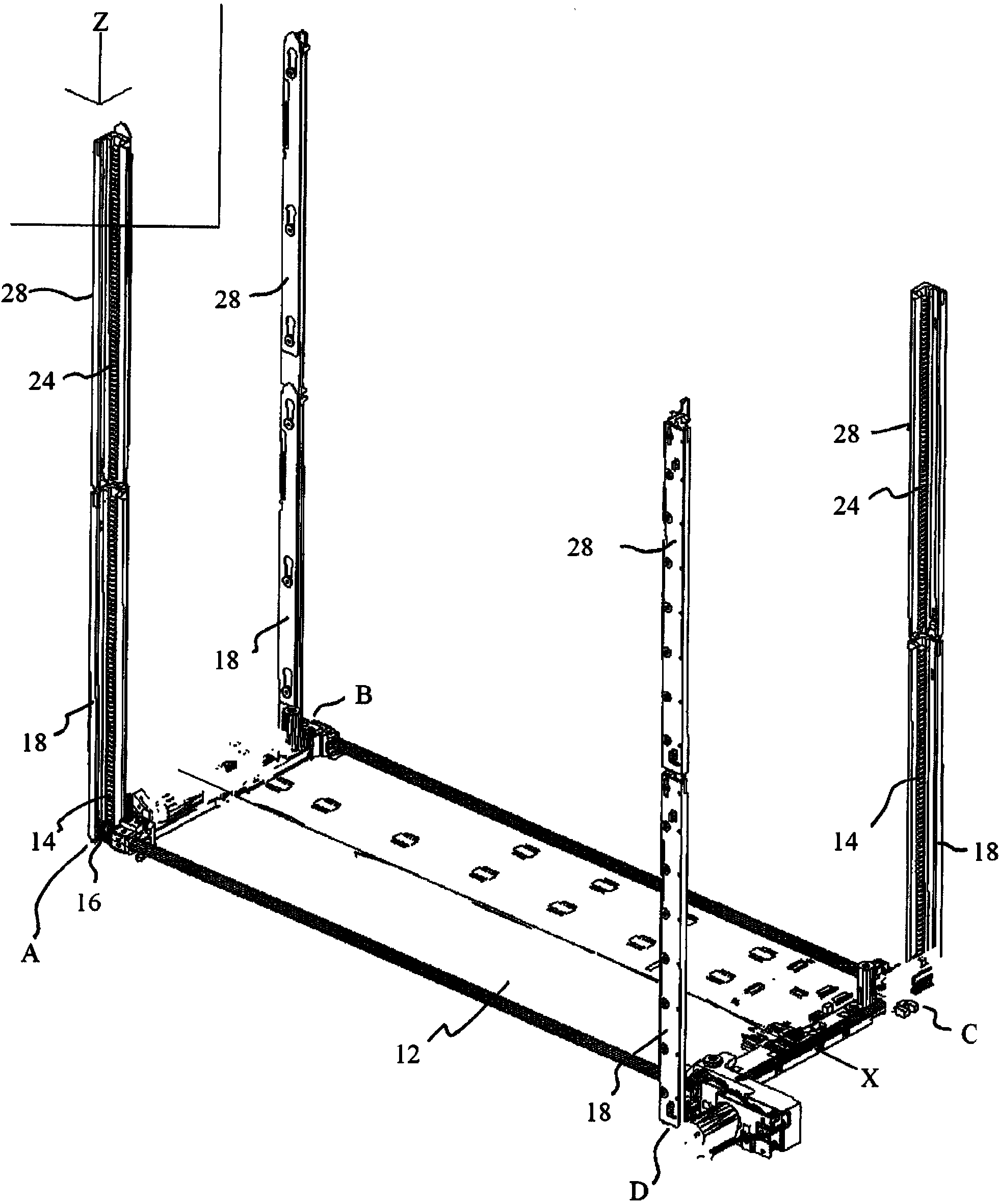
[0044] Combine the following Figure 1 to Figure 11 A typical transmission device 10 is described in detail.

[0045] like figure 1 As shown, the transfer device 10 is generally symmetrical about the horizontal axis X. As shown in FIG. The transport device 10 comprises a rectangular tray 12 for transporting the cassettes. The four corners A, B, C, D of tray 12 are provided with pinions or positioning pinions 16 very adjacent to, adjacent to or close to itself. In this way, the tray 12 is rotatably connected with four positioning pinions 16 .

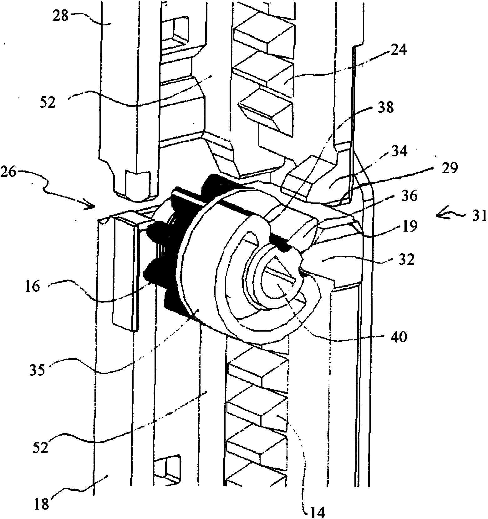
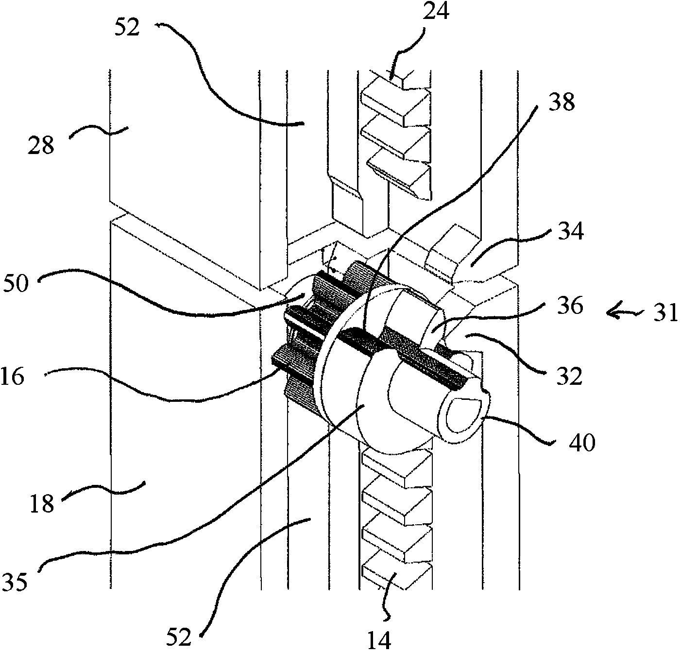
[0046] Four positioning pinions 16 are configured to rotatably vertically or uprightly engage racks 14, 24 disposed at the end of each database unit in a database unit stack (not shown). corresponding four corners. Therefore, each database unit is provided with four racks 14 or 24, and the positioning pinion 16 is engaged with the racks 14 or 24 respectively, so as to make the tray 12 in the database unit move and precisely position...


PUM


Abstract

A transmission apparatus for use in a stack of data library units, the stack comprising a lower data library unit and an upper data library unit, each data library unit of the stack comprising a plurality of upright frames, the transmission apparatus comprising a tray for transporting a tape cartridge; a plurality of positioning pinions rotatably attached to the tray; a plurality of racks each disposed on each of the plurality of upright frames and configured to be engaged by the corresponding plurality of positioning pinions for vertical positioning of the tray within each data library unit; a plurality of partial racks each comprising an upper tooth and a lower tooth disposed adjacent the plurality of racks at each of the plurality of upright frames, the upper tooth being disposed adjacent a lower end of the frame of the upper data library unit and the lower tooth being disposed adjacent an upper end of the frame of the lower data library unit; a plurality of cross-over pinions each rotatably attached to the tray and disposed co-axially with each of the plurality of positioning pinions, each cross-over pinion having a tooth profile configured to engage each of the partial racks for effecting movement of the tray between the lower data library unit and the upper data library unit.

Description

technical field [0001] The present invention relates to a transport device for handling magnetic tape cartridges and in particular, but not exclusively, to a transport device for handling magnetic tape cartridges in a stack of database units. Background technique [0002] A transport, typically having a tray that supports the vertical movement of a loading robot to access multiple tape slots in a database. In some embodiments, the tray can be moved up and down by a rack-and-pinion system, in which a positioning pinion rotatably mounted on the tray engages the rack. The rack is vertically arranged on the casing of the database. [0003] Typically, one database unit has one transmission device. To increase storage without substantially increasing cost, each database unit in a multi-database unit includes multiple tape slots, and one database unit is stacked on top of the other, forming a multi-database unit stack. In this way, it is possible to use only a single transport d...

Claims


Application Information

Patent Timeline
Patent Type & Authority Applications(China)
IPC IPC(8): G12B1/00
CPCG11B15/6835G11B33/04G11B17/225
Inventor 陈威健霍家和林永权王志德马登·普世帕卡斯魏晓阳
Owner VENTURE CORP LTD
Why Eureka
Try Eureka