
Pressure type optical fiber micro-change sensor

A sensor and pressure-type technology, which is applied in the field of optical fiber displacement sensor, can solve the problems of easy failure and inaccurate measurement of displacement sensor, and achieve the effect of avoiding the interference of the surrounding environment, high measurement accuracy and high resistance to electromagnetic interference

Pending Publication Date: 2019-01-04
CHENGDU KAITIAN ELECTRONICS
View PDF10 Cites 4 Cited by
  • Summary
  • Abstract
  • Description
  • Claims
  • Application Information

AI Technical Summary

Problems solved by technology

[0008] The technical problem to be solved by the present invention is to provide a fiber-optic micro-displacement sensor with larger measuring range, higher measurement accuracy, anti-electromagnetic interference, and high-temperature resistance in view of the deficiencies of the existing technology, so as to solve the problem of the current displacement sensor at high temperature. Inaccurate measurement in the environment, prone to failure and other problems

Method used


Image

  • Pressure type optical fiber micro-change sensor
  • Pressure type optical fiber micro-change sensor

Examples


Embodiment Construction

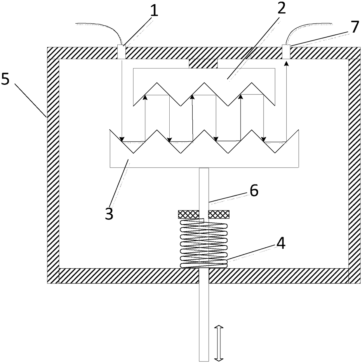
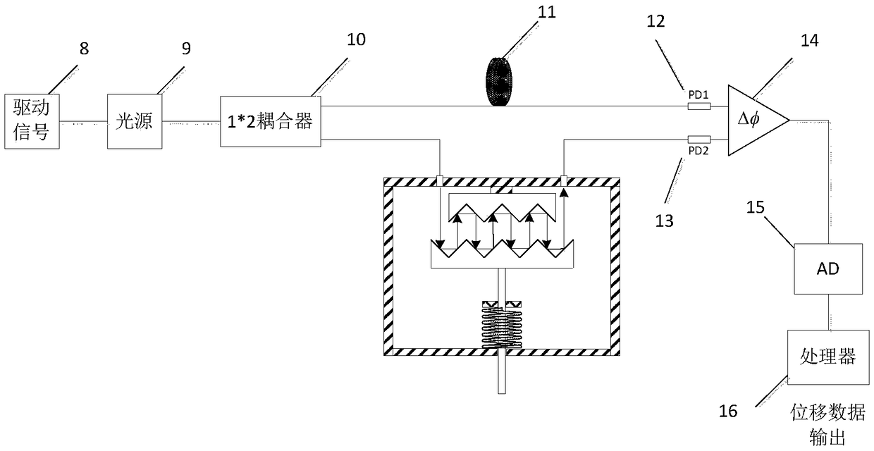
[0019] refer to figure 1 , figure 2 . In the embodiment described below, a pressure-type optical fiber micro-variation sensor includes: a signal modulation part, a displacement measurement part and a signal demodulation part, wherein the measurement part includes a cavity 5 surrounded by a rectangular frame, from the rectangular frame The bottom is inserted into the transmission rod 6 of the cavity 5, and a set of parallel lower moving tooth plate reflectors 3 fixedly connected by the spring 4 sleeve transmission rod 6, the upper fixed tooth plate reflector 2 as a displacement measuring element, and the lower movable tooth plate are arranged on the Above the back end of the plate reflector 3, it is symmetrical to the first collimating lens 1 and the second collimating lens 7 on both sides of the upper fixed tooth plate reflector 2, and the lower movable tooth plate reflector 3 and the upper fixed tooth plate reflector 2 are serrated The phase is symmetrical, and the couplin...


PUM


Abstract

The invention provides a pressure type optical fiber micro-change sensor, which can solve the problems of inaccurate measurement and easy failure of a displacement sensor at present in a high temperature and strong electromagnetic environment. The pressure type optical fiber micro-change sensor is realized according to the following technical scheme: light signals modulated by a signal modulationportion are divided into two beams through optical fiber coupling, one beam of light signals directly reaches a photoelectric detector through an optical fiber ring to serve as a reference light pathof an optical fiber light path, the other beam of light signals enters a lower tooth groove reflecting angle of a lower moving toothed plate reflecting mirror through a first collimating lens and is reflected to an upper tooth groove reflecting angle of an upper fixed toothed plate reflecting mirror through a completely reflecting mirror formed by tooth grooves, the incident light is reflected formultiple times by multiple tooth angles and enters a photoelectric detector pd2 connected through an optical fiber from a second collimating lens, and the light path serves as a measurement light path. The displacement change will cause the phase change of the light signals of the measurement light path relative to the reference light path, and the displacement change can be demodulated through detecting two phase variations by a phase comparator.

Description

technical field [0001] The invention relates to an optical fiber displacement sensor for measuring micro-displacement greater than 100mm, in particular to an optical fiber displacement sensor for measuring micro-displacement with high precision and large range. Background technique [0002] Optical fiber sensing technology is a new type of sensing technology that perceives and transmits external measured signals with light wave as the carrier and optical fiber as the medium. The main problem of fiber optic sensors for practical measurement is the long-term drift effect. The drift effect of the fiber optic sensor comes from the attenuation of the fiber optic transmission line, the imperfect characteristics of the coupler and beam splitter, the unstable output of the light source and the influence of the detector. The research of a single optical fiber sensor has entered the practical stage, but it cannot be applied to the measurement of multi-parameters and multi-variables, ...

Claims


Application Information

Patent Timeline
IPC IPC(8): G01D5/353G01K11/32G01L1/24
CPCG01D5/353G01K11/32G01L1/24
Inventor 代勇波谭银银常天宇
Owner CHENGDU KAITIAN ELECTRONICS
Learn More